Continue to Site

Eng-Tips is the largest engineering community on the Internet

Intelligent Work Forums for Engineering Professionals

  • Congratulations KootK on being selected by the Eng-Tips community for having the most helpful posts in the forums last week. Way to Go!

Rafter without fly brace? 22

Status
Not open for further replies.

fourpm

Industrial
Oct 12, 2019
13
I am designing rafters to AS4100 and wondering what if I don't use fly brace. I understand that with fly brace it will give you full restraint. But if I don't use fly brace, will the purlin above be considered as lateral restraint for rafter under uplift? If so. can I take the purlin spacing as segment and the only factor that changes without fly brace is kt?
I have the same question when it comes the continuous steel floor beam design where Z/C floor joints sit on top of the beam. What segment should I take for the beam near the support? Can I take the floor joists spacing as segment with lateral restraint? Can anyone give me some examples? I have read some manuals but the examples they have are simply supported beams only. Thank you.
 
Replies continue below

Recommended for you

KootK said:
Can you not do it just as we've been doing it in Mastan to date, by constructing faux frames in the shape of cross sections?

That's an example of what I meant by "a more detailed model that would include warping effects anyway".

But I will try and have a look at comparing Mastan (which includes warping), my spreadsheet and a "faux frame" without warping.

Doug Jenkins
Interactive Design Services
 
IDS said:
That's an example of what I meant by "a more detailed model that would include warping effects anyway".

I'm not seeing it IDS. As I see it:

1) If your true beam elements aren't formulated to include warping, none of this fax cross section frame business is going to do anything to approximate warping behavior and;

2) If your true beam elements are formulated to include warping, it's going to be represented whether you've got the faux cross section frames or not and the faux cross section frames would be unlikely to impact the results meaningfully.

What am I missing?
 
I think further insight can be gained by examining the sub segment approach of AS4100. This is something I intend on doing myself but I'm putting it out there for early comment or anybody else also do it. To do this properly though it is going to take time.

Examine the FEA buckling results vs 4100 reference buckling moments starting with the most simple cases. This is to check the FEA results against theoretical. (I've already done most of this, all looks good, AS4100 is approximately 10% conservative.) The goal is to establish the baseline FEA vs AS4100 reference buckling model for a particular model. This has been examined by quite a few papers, AS4100 reference buckling moment is generally considered conservative compared to FEA and conservative compared to other codes.

The next step is to compare the buckling predicted by FEA of a full beam segment. And then that of a sub-segment between lateral restraints in both simply supported cases and moment refersal cases. It would be expected that in the case of the former there would be minimal divergence, for latter there would be a significant divergence with AS4100 reference buckling moment being significantly unconservative.

This will take a while to parse. But I've already started. AS4100 goes amiss on effective bending lengths in cases of moment reversal, it would be useful to flesh this out properly.
 
Agree it needs to be fleshed out. We need to find out under what conditions the beam rotates at L-restraints. If the beam does rotate at the L restraint then AS4100’s assumption that the L restraints define buckling length is incorrect.

Human said:
And then that of a sub-segment between lateral restraints

I’m not sure you can look at these subsegments themselves, as it’s the assumption that they define buckling length that’s in question here. I think it makes sense to look at full beams, and identify the scenarios in which the L subsegment approach is valid, I.e. identify the situations where L restraints produce the same buckling mode as F restraints.

Agree it is likely to flip from OK in simply supported cases to NOT OK in some moment reversal cases. I’d like to see the effect of beam dimensions too. Overall dimensions, as well as plate dimensions. I’ve been planning to do it too, in Mastan. But yeah, it’s a lot of work. It’s something a PhD student should be doin to be honest, backed up with experiment.
 
@Tomfh: FYI, I'm making an attempt to cast a broader net to see if we can track down some testing: Link

@Celt83: did you ever hear back from AISC on your inquiry? I'm curious to know their answer if you have.

@Everybody: I may reach out to Trahair to see if I can't bait him into providing some insight. I know that sounds a little nuts but I've actually had pretty good success doing this in the past. That said, if anybody else has already done this, do let me know. While I'm always up for finding another antipodean to exasperate, I don't want to be the sixth random guy from the internet to harass him on this.

Consider playing chess with me on the Social Chess app at iTunes. Same handle. Fear not, I suck.
 
I did here is what they said:

AISC Response said:
We cannot make design decisions. Note that Section 6.3 of the AISC Specification states “In members subject to double curvature bending, the inflection point shall not be considered a braced point unless bracing is provided at that location.”

Also note that if you can justify the top bracing as torsional bracing, it would not need to be located near the compression flange, as stated in Section 6.3.2.

I have addressed your questions below in red:

What would be the determination of Lb for such a beam? I believe an unbraced length equal to the full span, 32’, would be an acceptable approach.

Or is this a case where the standard formulas in Chapter F would not be applicable and a buckling analysis should be performed?
I think you could apply the formulas in Chapter F, but would have to do so using the full unbraced length. Other approaches could be considered as well (such as the buckling analysis you refer to).

The commentary to Section F1 provides some guidance on the calculation of Cb that may be helpful as well.

Open Source Structural Applications:
 
@Celt83: thanks for that. I can see why you didn't bother to report back. Can I lay claim to an "I told you so"?

Consider playing chess with me on the Social Chess app at iTunes. Same handle. Fear not, I suck.
 
KootK said:
I may reach out to Trahair to see if I can't bait him into providing some insight. I know that sounds a little nuts but I've actually had pretty good success doing this in the past.

I agree it makes sense to consult directly with some experts.
 
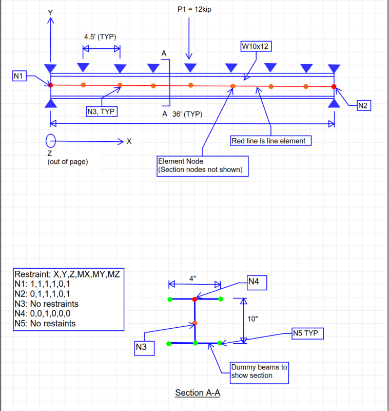
I wasn't able to edit the post, so here is the test beam again.

KootK - have you reached out to Ziemian at all?


Test_Beam_V2_tsb3wq.png


PDF

EIT
 
RFreund said:
KootK - have you reached out to Ziemian at all?

Nah, to date I haven't reached out to anybody outside of this thread. Interestingly, in the companion thread that I started, some other options for software have come to light. A package called LTBeam seams perfect for this and, if anything, might be more suited to production work than Mastan. I might give that a go.

Consider playing chess with me on the Social Chess app at iTunes. Same handle. Fear not, I suck.
 
Yes it'd be interesting to see what LTBeam has to say, compared to Mastan and nastran. So far both Mastan and NASTRAN agree AS4100 can be unconservative. The more computation results the better. These programs, like eng-tips participants, bring their own particular spin which helps shed light on the underlying phenomena.
 
Quick question to Kootk:

When you posted Cb_Yura here:
Kootk said:
To provide a more meaningful comparison, I reran the beam as fixed ended with a uniform load.

M_LTB_Mastan_Concentrated = 690 k-ft

M_LTB_Mastan_Uniform = 854.2 k-ft

Cb_Yura = 3.00

M_LTB_Celt83 = 919.4 k-ft (Your calc adjusted by ratio 3.00/3.67)

854.2 k-ft / 919.4 k-ft = 93%. As approximate as this stuff is, that's a non-discrepancy in my book.

What is this referencing? Or what equation is this?

EIT
 
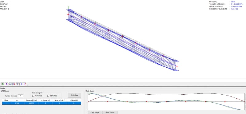
I just ran a quick one in LTBeam and its showing the bottom flange kicking out again at longer effective length than AS4100 assumes.

Loading is central point load, with fixed ends (free to rotate in plan)

CAPTURE_whucmo.jpg


I haven't compared the actual numbers against AS4100 yet...
 
RFreund said:
What is this referencing? Or what equation is this?

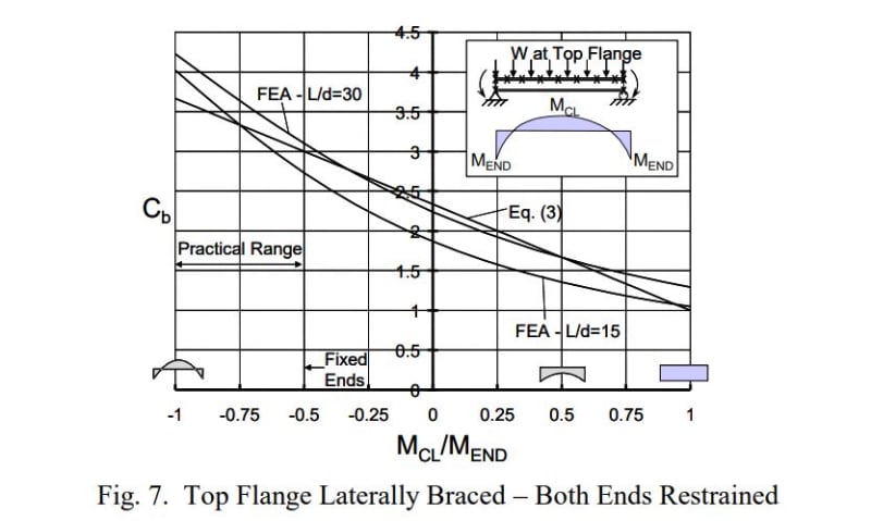
It's a equation/graph from the Yura paper that I attached to one of my posts early on in the thread.

It seems to be the modern AISC approach to lump many of the complexities into the Cb factor, including load height and lateral only bracing impact. I think that it's a bit of a departure from the very old school stuff where Cb was solely about the impact of the disposition of the bending moment along the segment being studied.

c03_ef87yc.jpg

c02_xstuj6.jpg


Consider playing chess with me on the Social Chess app at iTunes. Same handle. Fear not, I suck.
 
Interim update:

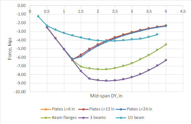
I have been doing some analyses using Strand7, and get widely varying results, depending on how I model the beam. The options I have looked at are (in order of increasing complexity):

- Linear longitudinal beams with beam offsets to the top flange
- Longitudinal beams for top and bottom flange connected with vertical beams
- Longitudinal beams for top and bottom flange connected with plate elements
- Plate elements with 3 levels of plate size

I carried out an incremental displacement analysis with geometric non-linearity, and got the results shown below:
Beam_buckling1_oqhxof.png


Only the plate models showed a clear buckling load, although the beam models were also highly non-linear.
The buckling load of about 6.2 kips agrees pretty well with my LTBeamN analysis, but the elastic critical load from Mastan2 was much lower, and the elastic buckling load from Strand7 was much higher.

Looking at the LTBeam report on validation tests (linked earlier) all their results agreed with Ansys and Drill within about 0.5% (!). I am going to run some of the examples from the validation report in Strand7 and see what I get.

I'll post more details next time, but the model was as shown in Rfreund's post of 17 Dec, except with a 32 foot span.

Doug Jenkins
Interactive Design Services
 
Human909 said:
EG: 46m 610UB101 with single lateral brace at the top flange in the centre
LOAD FACTORS:
AS4100: 1.01 (PLP & FLF)
NASTRAN: 0.753 (PLP) (No minor axis or flange restraint at ends, no twist restraint at lateral brace)
NASTRAN: 0.757 (PLP) (No minor axis or flange restraint at ends, twist restraint at lateral brace)
NASTRAN: 2.59 (FLF) (Full end restraint, twist restraint at lateral brace)


I ran this scenario in LTBeam.

LTBEAM: 1.526 (FLF) (Mcr = 266.4kNm)

According to LTBeam the AS4100 clauses work in this instance.
 
Sorry for bumping this, but the AISC journal has a paper in it this quarter on constrained axis buckling and application with AISC that might be of some interest to some contributors in this thread.

 
Thanks Agent666. I was surprised that anybody had the temerity to bump this back into 2019 but that was certainly a worthwhile contribution.
 
I think this thread should keep going. We haven’t gotten to the end of it yet.

I’d be interested in identifying a clear cut example of an Australian beam that fails AS4100, ie the predicted capacity using the segment method exceeds the theoretical buckling moment.

The 610UB example under self weight appears to work under LTBeam, but not in NASTRAN?
 
Status
Not open for further replies.

Part and Inventory Search

Sponsor