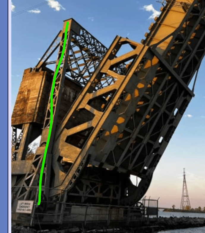
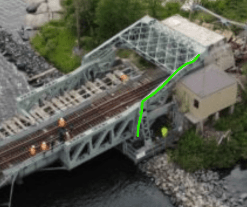
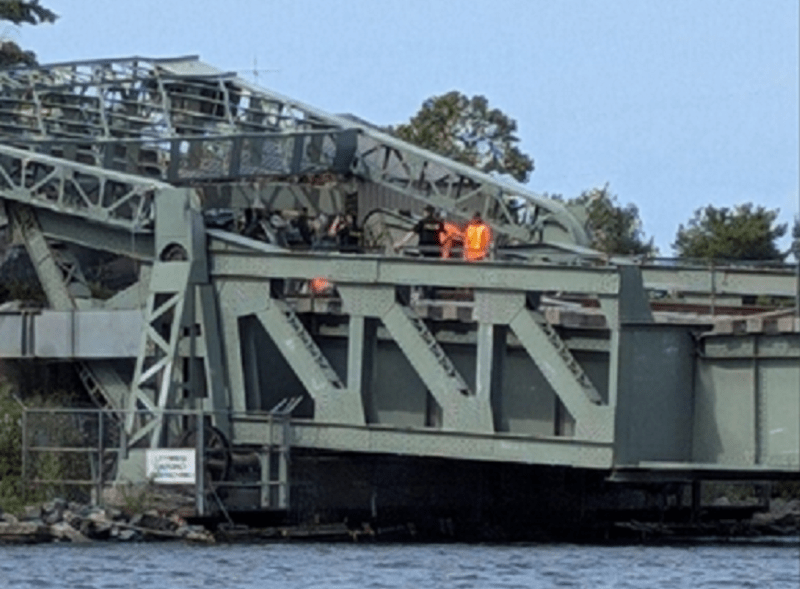
Anyone has more info on this bridge collapse? Did it collapse while lifting? Any info is appreciated.
Navigation
Install the app
How to install the app on iOS
Follow along with the video below to see how to install our site as a web app on your home screen.
Note: This feature may not be available in some browsers.
More options
Style variation
-
Congratulations TugboatEng on being selected by the Eng-Tips community for having the most helpful posts in the forums last week. Way to Go!
You are using an out of date browser. It may not display this or other websites correctly.
You should upgrade or use an alternative browser.
You should upgrade or use an alternative browser.
Rail bridge collapses near the US-Canada border 9
- Thread starter TORCHMAN
- Start date
- Status
- Not open for further replies.
-
4
- #21
-
4
- #22
- Moderator
- #23
I am in agreement with 3DDave and OOps409.
This is a parallelogram mechanism.
The vertical structure (gantry?) does not move, It is the one rigid side of the parallelogram.
It is possible to design it with no lateral loading other than wind loading.
While it may not be designed for completely zero lateral loading the loading will be very low.
Given a combination of serious corrosion and a powerful wind storm, it may have deflected.
Once it deflects, the lateral loading will increase and it may proceed to destruction.
--------------------
Ohm's law
Not just a good idea;
It's the LAW!
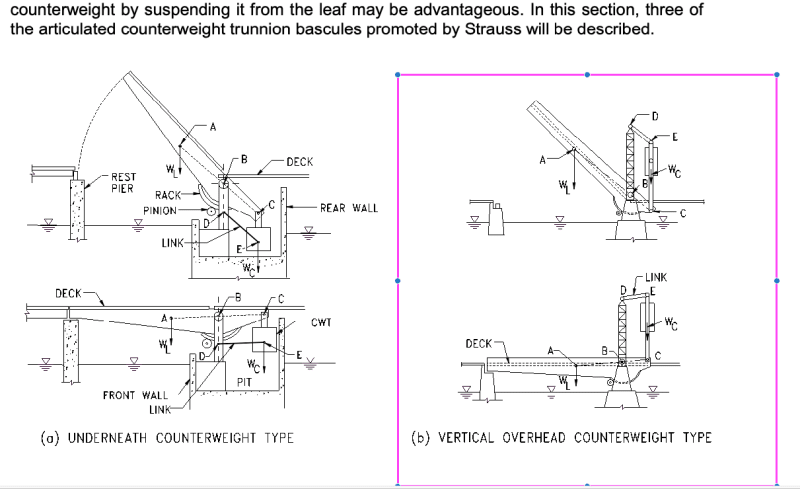
Here is the complete paragraph to go with the drawing above, from a Wisconsin Structural Inspection Manual for Chapter 3.2 Bascule Bridges. Link to pdf uploaded
"3.2.4 Articulated Counterweight Bascules – Strauss Type
Medium and long span simple trunnion deck bascules with the roadway profile close to the high-water level generally require bascule piers with counterweight pits. The walls of the bascule piers keep the water from entering the pits and so provide dry spaces for the counterweights as the bascule leaves rotate open. This is also the case for rolling lift deck bascules, but to a lesser extent. Counterweight pits can be avoided if the counterweights are located remote from the bascule girder, usually overhead.
Trunnion bascules may be balanced by counterweights that are not fixed to the bascule truss or girders. This concept is old, but U.S. Patents for bascules with remote counterweights were granted to Joseph B. Strauss around the year 1900 and bridges with his specific counterweight arrangements are often called Strauss bascules. Three common versions are shown in Figure 3.2.4-1. The distinguishing feature of all Strauss bascules is the parallelogram connecting the counterweight to the movable leaf. In all Strauss bascules the motion of the leaf is by rotation about a fixed horizontal axis.
In some situations, it is not the depth of the required pit but the front-to-back dimension of the pit that needs to be minimized, as in Figure 3.2.4-1 (a). In such cases articulating the counterweight by suspending it from the leaf may be advantageous. In this section, three of the articulated counterweight trunnion bascules promoted by Strauss will be described."
- Moderator
- #27
A theory:
The bridge was lowered to allow a train to pass.
That would have put the counterweight in the upper position.
The bearings on the gantry end of the links seized or jammed.
As the bridge was raised, the counterweight lowered and the jammed bearings imparted a torque to the gantry structure that caused it to topple towards and on top of the counterweight.
Root cause:
Corrosion damage to both the gantry and to the bearings at the top of the gantry.
(Is gantry the correct term?)
--------------------
Ohm's law
Not just a good idea;
It's the LAW!
- Moderator
- #28
LittleInch
Petroleum
This is why I love this site - far better explanation than any of the news sites. Great find for the diagrams etc. Amazing really that this design is still functioning 115 years later.
Maybe you didn't click on my link a few posts above, but it seems 5 years ago the bridge was stuck in the down position for over 6 months. This is the interesting bit.
"When constructions workers returned to the Five-Mile bridge in the spring, Boivin decided to ask what the issue was and when it would be fixed.
“They said that during their maintenance and upgrades to the bridge, they discovered that some very important bearings down in the bottom had failed and were not passing the test,” stated Boivin.
“They said the bridge would not be open until July 5.”
I think if any of the main joints, be it the main bridge joint or the ones connecting the counter weight to the bridge or the vertical structure seized or was creating a lot more friction, the torsional effects would just bend this thing apart. That vertical metal structure looks relatively weak compared to the weight of the counterweight so any serious forces would cause it it bend and then it just gets worse until it falls over.
It might not help that it looks like it was designed for a double track lift, but they lifted the rails and some of the sleepers on one side. Might be small, but for something as delicately balanced as this might make a difference long term?
Remember - More details = better answers
Also: If you get a response it's polite to respond to it.
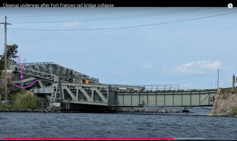
I lean towards the thin vertical leg supporting counterweight to the lever arm in the forefront of waross's picture failed. Thus causing the loss of support and torsion loads on gantry. Notice forefront side is collapsed lower than the other side. Thus also loss of counterweight to hold bridge up. Or pin connection failure at lever arm connection.
LittleInch, no fault of yours; when I went to that link I got a nearly full page "please subscribe" and skipped it. Thanks for the text extract. Quite informative.
I think being single track/other changes would only affect the load on the gear teeth and the attachment to the bridge; also a horizontal load on the main bridge bearings reacting the extra load on the gear.
I wonder if it was remotely operated or if someone sits in the little house all day awaiting a train and what they are doing with their time now.
LittleInch
Petroleum
Prob next to impossible to determine cause from effect here.
They might not even bother to find out...
I've seen somewhere on my travels that this line only has a couple of trains a day and is now automatic. Back int he day that little cabin was probably manned alright.
Remember - More details = better answers
Also: If you get a response it's polite to respond to it.
Any bets that bridge has been making noises it should have been for a while and that someone working there would have heard them? That they would have heard the motor make a little groan if a bearing got stuck that usually would only happen if the bridge was unbalanced by a heavy ice load? That it would have been stopped?
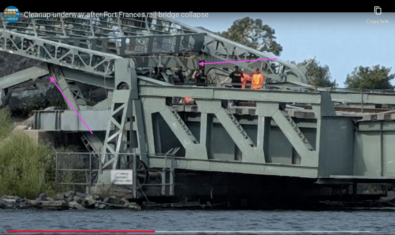
Slight Correction. Foreground pin connection from counter weight to lever arm (leaf) is still attached in picture. While the background vertical appears to be broken away and separated from the lever (leaf) arm.
Second pictures shows bent vertical support for counterweight, due to loss of connection on other side.
[URL unfurl="true"]https://res.cloudinary.com/engineering-com/image/upload/v1725034393/tips/patent_dkdqyb.pdf[/url]
Second pictures shows bent vertical support for counterweight, due to loss of connection on other side.


[URL unfurl="true"]https://res.cloudinary.com/engineering-com/image/upload/v1725034393/tips/patent_dkdqyb.pdf[/url]
- Moderator
- #36
The picture shows no contradiction to my theory.
The gantry and the top links serve to keep the counterweight CoG vertical over the lower pivot.
There is little side force on the gantry save for wind loading and possible slight construction errors.
Anyone who has ever held a heavy appliance balanced upon one bottom edge knows how little force it takes to keep the appliance balanced and how quickly the force needed multiplies as the object tilts away from the balance point.
When a link arm bearing seizes up on top of the gantry, the weight of the descending counterweight put an unanticipated force on the gantry.
Once the gantry deflected, the CoG of the counterweight shifted away from the vertical with respect to the lower pivot support.
That shift increased the unanticipated horizontal forces on the gantry and complete collapse was almost immediate.
The bottom of the counterweight support rests and is pivoted to the back end of the bridge deck extension.
As the gantry collapsed and the counterweight fell over, the counterweight supports would simply pivot without experiencing any great destructive force.
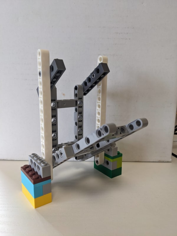
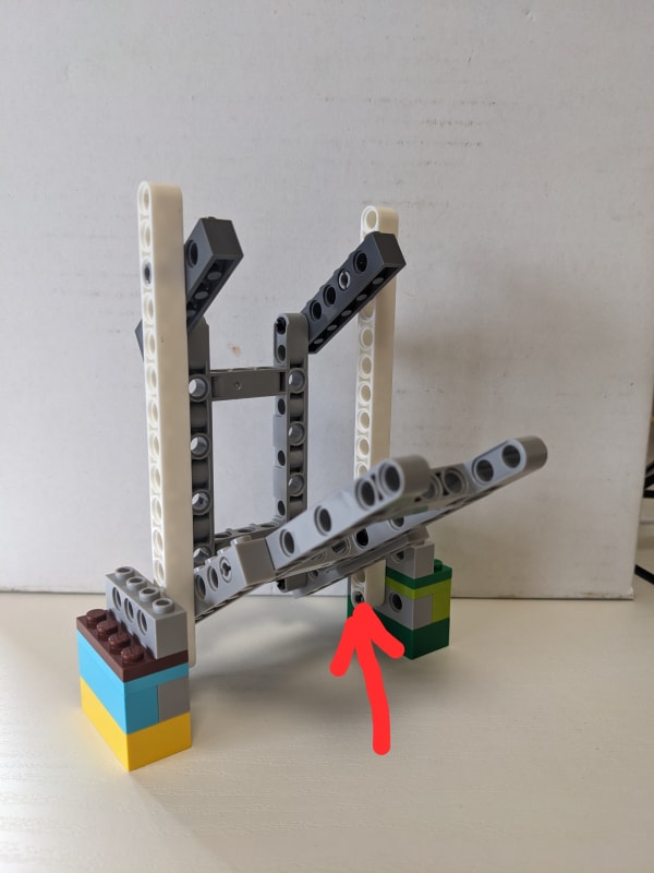
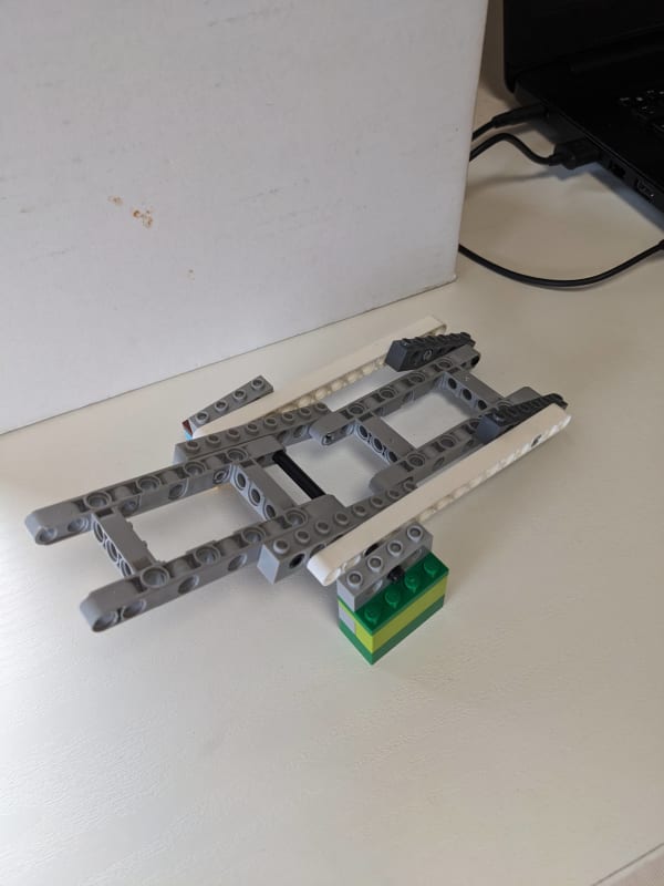
A suggestion MintJulep
A modification to your forensic model:
Weaken the white vertical members at or above the lower pivots to simulate corrosion deterioration.
I suggest cutting most of the way through the members with a hacksaw or something similar.
The model should still be able to function to simulate raising and lowering.
Now fix or pin the upper pivots on the white vertical members to simulate seized bearings and prevent rotation.
Do this with the deck in the down position.
Now, with the upper pivots unable to pivot as intended and the lower part of the white verticals severely weakened attempt to raise the deck.
I anticipate that we will see a failure similar to the actual event.
It may be interesting to actually load the arms simulating the counterweight with some weights.
The CoG of the added weight must be directly vertically above the lower pivots.
I anticipate that the model will function well with considerable weight even with the vertical supports compromised but that the model will collapse when the upper pivots are restrained.
Thank you for your consideration of this suggestion.
--------------------
Ohm's law
Not just a good idea;
It's the LAW!
-
1
- Moderator
- #38
- Status
- Not open for further replies.
Similar threads
- Locked
- Question
- Replies
- 4
- Views
- 5K
- Replies
- 17
- Views
- 1K
- Replies
- 4
- Views
- 2K
- Question
- Replies
- 27
- Views
- 28K
- Replies
- 1
- Views
- 5K

