Continue to Site

Eng-Tips is the largest engineering community on the Internet

Intelligent Work Forums for Engineering Professionals

  • Congratulations KootK on being selected by the Eng-Tips community for having the most helpful posts in the forums last week. Way to Go!

Rail bridge collapses near the US-Canada border 9

Status
Not open for further replies.
Replies continue below

Recommended for you

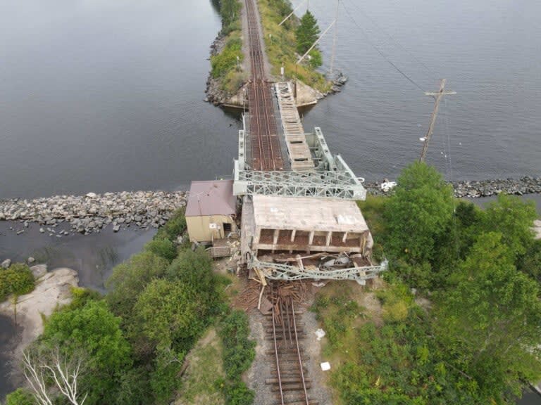
I have hard time explaining damage to building and ground below the stub end, if stub was fully attached when counterweight fell, and the sheared bolts happened after counter weight hit ground. My take is leg stub disconnected from bearing hub assembly while in air and slid off leaf into building doing ground and lower damage, prior to ending up horizontal and damaging building wall from ground up to resting point.

Notice also that the disconnected stub moved laterally into building, which also caused twisting of of the counterweight pivot connection on the other side.

Edit: Waross, I don't discount that there could have been issues at top of counterweight, as that is a hard area to inspect, and one that could go unnoticed for long periods of time. But I clearly think stub separation caused the twisting and over loading of the other counterweight upright.

More4_dqeu0h_mb69ah.jpg
 
Consider:
The bridge had been lowered.
The bearing at the top of the gantry may have done some damage to the gantry due to a jammed bearing, but not enough to bring the structure down.
As the bridge was then raised, the descending counterweight working through the frozen bearing, pulled the gantry over.
As the gantry fell over, the counterweight fell backwards.
The upper edge of the counterweight struck the ground first as the support members pivoted on the lower bearings.
The geometry was such that had the lower supports remained straigt and unbroken, the lower edge of the counerweight would have been supported above the ground.
However the counterweight supports did not have the strength in that position to support one edge of the counterweight above the ground.
As a result, the supports bent and then broke.
This would explain the alignment of the counterweight.
Had one lower pivot jammed and the support broken as shown and caused the counterweight to fall, there is a very high probability that the wreckage would be skewed to one side.

--------------------
Ohm's law
Not just a good idea;
It's the LAW!
 
waross, I do follow your logic, and I see that an upper issue could have been the initial domino, and any binding or loss of connection at one side of upper CW attachment could cause the shearing of bolts from stub to bearing connector assy. It appears in pictures that the bottom edge of CW on the side with bent lower support leg is touching ground, but the other bottom side is not. It also appears concrete CW contacted train rails, as you can see impact zone, then slid away from bridge pivot points, on building side, after it was on the ground.

But, I keep coming back to the image above and can't explain building damage below CW lower support stub. I do believe counterweight is skewed laterally into building and it has fallen further away from from counterweight lower pivot point. I can't tell for sure, but it appears the lower CW support leg may be bent inward towards the other support leg? Also the side away from building has collapsed lower to ground than building side.

The stub does not appear to have contacted pit wall on building side, like the other side, which indicates perhaps a lot of torsional and lateral movement in the gantry and CW assembly before splash down or on the way down.

It appears CW had to maintain some sort of connection at the top to the gantry to be able to pull the gantry down. Perhaps one side failed and the other side did not? I do feel the damage is skewed towards building and away from pivot point on building side.

I give up, I have exhausted all the brain cells I have, and I still cannot see any conclusive answers from the available data set....

454721229-3412409745726460-6104086313984956613-n-768x576_pyj2nu.jpg


454063060-1192267351921376-7925589926700963340-n-768x576_isa5kb.jpg
 

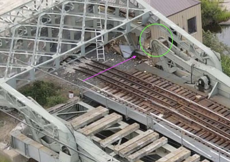
Arrow points to upper gantry bearing which detached and fell down. The proximal green (greyish) parts are from the upper gantry arm.
 
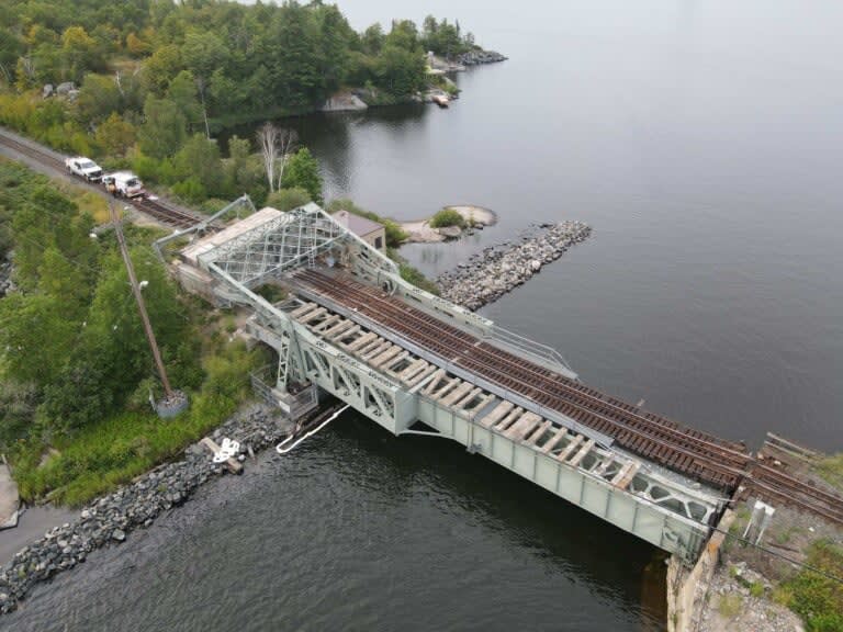
Looking at 409s picture above this double track bridge could never have operated that way looking at the single track causeway. So 115 years of slightly off balanced load had an effect?

The balance forces are very tightly matched to achieve low opening and closing on the rack and pinion so did this slight difference in lift force one side to the other just finally catch up with it?

Remember - More details = better answers
Also: If you get a response it's polite to respond to it.
 
Thanks for those final missing pieces that I could not see in images! Binding/failure and detachment of upper gantry control arm and asymetric loading fills in the missing pieces. Also notice all the scrap rails that spilled out of counterweight on building side of CW that was added to counter bslance heavier track side.

 
In the end, a tired old structure that got away on them. A feint blip in the budget of CN Rail, they just shrug and barely consider their luck in not maiming anyone or worse. To the locals, an insult, interruption and inconvenience to their quiet and semi-remote way of life.
 
Rail bridge to resume service by mid-September

Temporary Quick Bandaid Fix to get trains running by mid Sept 2024. Wonder if they are going to just weld on some shims and cross beams to the bent bridge to provide level platform for new track, and use existing bent, buckled bridge substructure, as is, in a fixed configuration?

Edit: the audio version confirms use of existing substructure as fixed temporary bridge. I imagine they will build the new bridge beside this bridge, and shift tracks to it when it is complete. Therefore likely the land owners without roads to their properties are going to be without boat access either for an extended period of time.

 
Oops409 said:
Temporary Quick Bandaid Fix to get trains running by mid Sept 2024. Wonder if they are going to just weld on some shims and cross beams to the bent bridge to provide level platform for new track, and use existing bent, buckled bridge substructure, as is, in a fixed configuration?

Edit: the audio version confirms use of existing substructure as fixed temporary bridge. I imagine they will build the new bridge beside this bridge, and shift tracks to it when it is complete. Therefore likely the land owners without roads to their properties are going to be without boat access either for an extended period of time.


No need to weld shims or anything and bring it back to level; Just wasted resources.
We've run fully loaded trains over near instant 4" rises in grade before. Just lower the speed limit and everything will be fine. Clear the debris, replace the timbers, tie plates and hardware, lay some new track, maybe notch some timbers to ease the transition, weld some plates on the front to anchor points at the bent, lay some dunnage down below at the rear, and weld/patch what ever areas need repair from damage down below. 10-15 days and you got trains running, possibly less. Most time consuming is going to be cutting the counterweight for removal. It's most likely full of old rail, rivet buttons, and old steel scrap packed as tightly as possible. Not fun for the core drillers and diamond rope guys.

The bridge fell, but doesn't look like it fell all that far. I wouldn't be surprised if they just replace the counterweight mechanism, patch/repair buckled and cracked areas, and stiffen other areas overtime, and keep a perfectly good bent bridge with a 20mph limit.
 
Status
Not open for further replies.

Part and Inventory Search

Sponsor