Eng-Tips is the largest engineering community on the Internet

Intelligent Work Forums for Engineering Professionals

Rail bridge collapses near the US-Canada border 9

Status
Not open for further replies.
Replies continue below

Recommended for you

Oops409 (Mechanical) 30 Aug 24 02:33 [URL unfurl="true" said:
https://files.engineering.com/getfile.aspx?folder=e908db04-a45d-416c-bdd0-5[/URL]]
Lines B-D and C-E need not be vertical ...

More7_h6z6dv.jpg

The vertical tower structure will always be loaded in a skewed system. Couple that with acceleration forces during operation (the counterweight is alternately drawn towards or pushed away from the tower structure) and countless storm wind forces over the years, the tower was just plumb tuckered out.

More_aqen6z.jpg


More2_quw2g0.jpg


The vertical counterweight support somehow sheared or tore above the bearing connection while the stub flopped down to its final resting position.

More4_dqeu0h.jpg
 
Great image finds that show the vertical counter weight separation, or break from the pivoting connection

Symple, I agree that the two parallel verticals B-D and C-E will not always be vertical due to arc of leaf they are attached to, and I agree to that over 100 years of use might be beyond useful life without good maintenance and repairs over the years of everything.

Great image finds that show the vertical counter weight separation, or break from the pivoting connection.

I also agree the vertical legs from the leaf to the counter weight are always under constant load.

So that leaves a clear question as to cause and effect. Did the break of the vertical counter weight steel column break first at leaf connector, or did the vertical gantry fatigue first and start the lateral movement that caused the break in the counter weight vertical?


As I pundicated, the gantry buckled first. This creates a runaway system where the counter weight leans away from and looses its influence over the span which then offloads more energy into the system. It would have been quite spectacular to be in the control house.
 
Lines B-D and C-E need not be vertical

True, but why would it be designed to be not vertical? Vertical will be the simplest design solution unless there are extraordinary factors cause the need for not vertical.

Oops409 said:
I agree that the two parallel verticals B-D and C-E will not always be vertical due to arc of leaf they are attached to,

This is not correct.

B-C and D-E are equal length and parallel. Thus, B-D and C-E will also always be parallel. If they were designed vertical (and certainly they were), then they will always remain vertical. (until of course the bridge falls down).

The break at pivot C is a good find. If that was the initial failure point then I can see how it would introduce some twisting around the vertical axis of the gantry structure because that side of the linkage is no longer constrained to being parallel.

@waross
Your suggestions are interesting, but I'll not be cutting my Legos - I have too few good Technic pieces as it is.
"Weaken the white vertical members at or above the lower pivots to simulate corrosion deterioration." My initial experiment effectively did this anyways. It introduced a hinge at that point, where by design a hinge is not desirable.
I think the ratio between friction forces and gravity forces of Lego vs the actual bridge are very different, so the remainder of your suggested experiments aren't likely to scale correctly.

 
Mint, Notice the center line of the trunnion axle that the bridge pivots on is not in same vertical plane as the upper hinge point at gantry.

Then the length of upper control arm does not appear to be same length as lower control arm (leaf of bridge) nor are those control arms parallel to each other.

Thus the counterweight is not moving up and down in a perfectly parallel plane with gantry


More_aqen6z_euwozw.jpg
 
Excellent illustration Mint. I agree that any mechanical issues could stress the towers and lead to the collapse. That includes abnormal accelerations/decelerations.
 
Mint, I think your illustraion with a failed pivot C shows how the vertical support for the counterweight on the other side got bent before/during collapse.

I still lean towards failed connection at pivot C causing load transfers to rest of structure. The gantry legs bent like malleable steel that was overloaded laterally.

 
Oops409 said:
Mint, Notice the center line of the trunnion axle that the bridge pivots on is not in same vertical plane as the upper hinge point at gantry.
I had to think about this for awhile.
MintJulep's link to "A wealth of images of Strauss Bridges." helped a lot.
What should be done to minimize or eliminate unwanted horizontal forces is;
The CoG of the counterweight should be directly above the supporting pivot.
The links should be of equal length so that the CoG of the counterweight remains be directly above the supporting pivot throughout its travel.
It is not required that the pivots be in a direct vertical line as long as the mechanism is a true parallelogram, there need be no designed horizontal forces throughout the travel.

As far as the broken counterweight support, That would be only in compression during normal operation.
(The vertical counterweight support somehow sheared or tore above the bearing connection while the stub flopped down to its final resting position.)
The break had to be subsequent, not causative.

--------------------
Ohm's law
Not just a good idea;
It's the LAW!
 
Yes vertical supports are all ways in compression, but the horizontal vector forces are changing with movement of contol arms. I think when counterweight leg fractured at C, it walked off end of leaf connection.

Can't tell clearly from picture, but it appears it may have been bolt failures that attached 'stub' to bearing connection assembly.

Edit: I am surprised no one has mentioned Strauss was Chief Engineer for the Golden Gate Bridge, later in his career.

4209C032-350E-4CA5-BCCA-5C0CB05F00E9_r0yyex.png
 
The bridge apparently had bearing work conducted during Winter and Spring 2019.

Repairs_h3j1gg.jpg


Finally reopened at end of July 2019.

From_Rainy_Lake_boats_q2jlp0.jpg


I'm wondering if the counter weight has been beefed up behind its vertical support. Would this not place additional strain on the support columns and pivot tower? To my eye, the pivot tower looks out of plumb in many images.

The main bearing looks like it blew a gasket. Is that cause or effect? Also of note, the south vertical support appears broken just above the bearing connection similar to the north vertical. I suspect there was a transition that was vulnerable to the massive counter weight moving horizontally as it slammed down on the tracks.

bearings_wbyyrg.jpg
 
The vertical support brace was damaged from contact with the pit wall (where the inspector is standing). This indicates that the bridge was fully lifted when the counter weight/pivot tower fell over. Similar damage is visible on the north side as well.

Brace_damage_mbzkks.jpg


We can also see upgraded structural steel, likely from the 2019 work. CN didn't get much bang for their bucks, ... or maybe more than they bargained for?

Modern_Steel_e7zjpp.jpg


Original steel frame work. This image also shows the proximity of the damaged brace to the pit wall when the bridge is in the lifted position.

Modern_Steel.old_owuf3g.jpg
 
Symple,

I just gotta ask what search engine or search tools are you using to find these deeply buried images? Either you are using some great open source tools or created your own, or you have an insider source for these images..... The Censored and Monetized Commercial Search Engine's today, only find information that puts CASH in their pockets!

I would like acknowledge that littleinch found article on bearing work in 2019 and posted above, and 3DDave mentioned V-configuration in an earlier post......

I need more time to fully digest your new images, but on surface I find things my eyes indicate may be flaws in some of your conclusions?

I will have to mark up your images to show some different conclusions. That said, I fully agree the gantry columns are a very weak point in original design, right above the pivot point. Clearly if the massive counterweight changes in any way to put more horizontal stress right above the pivot point, then it is just a matter of time before that joint fails. Warcross's example of balancing an washer or dryer on edge is a great example of any slight changes to balance of counter weight really increases stress and fatigue on the gantry columns right above the pivot joint, and father time does a number on that joint too.

I agree that their replacement of the original taper truss horizontal brace with what looks like a beefier I-shaped beam, indicates that had either movement issues around pivot, or that tapered truss had decayed. And strengthening or arresting movement at that point, adds stress to gantry right above pivot point. Some of the pictures show the bridge in a very rusted and low maintained state, which may be the state it was in most of it's over 100 years of use.

As far as the grease below the apparent sleeve bearings, I think that is normal. They should be changing out grease over time by pumping in more fresh grease into zerk type fitting with the old grease been expelled out the ends of the sleeves, and some will be expelled during use. I would argue the sheet metal cover over the outside sides of pivot bearing are solely there to hide the expected grease on the outer ends, where people could spot the grease and complain...... Of course if they were doing more and better maintenance, they would clean up the extruded grease periodically rather than just let it work it's way into the soil and water way.

Edit: littleinch earlier wondered what someone did when it had a man in the shack before automation. I would argue it should have been that mans job to constantly maintain the grease joints, and inspect for damages or decay. Especially if there is only 1-2 trains per day passing.

 
Google (various search terms dancing around the subject matter), Facebook, reddit, twitter, and most important GIMP, which I've leveraged to draw out details in very dark shadows with screen layering and scaling.
 
Ok, by zooming in on Symple's images, I see lots of rivets in the sheet or plate steel cover that appears to have been added over the trunnion ends. Mostly around pivot point and upward. So this plate steel mend cover may have been added to strengthen a weakened and failing area at pivot joint, or was part of original design to add strength to this critical area. So unlikely to hide extruded grease.

The hole is probably there to allow inspection of new grease flowing out end of bushing, to ensure fresh grease inside sleeve bearing pockets. Only way to know if full of grease, it that fresh grease coming out ends.

This is common approach used on trailer axle hub bearings. Trailers have dust caps. If bridge is up, when it has s sudden failure, the fall rate and rotational speed is far greater on pivot point, thus significantly more heating of joint than normal slow controlled and balanced rotation. Thus more grease expelled.

 
I still believe that a top bearing seized and the descending counterweight pulled the gantry structure down. The rest is subsequent damage.
If the counterweight supports had not bent and broken they would have supported one end of the counterweight off of the ground.
While they could support the vertical counterweight in compression, when the counterweight fell to the ground the supports bent and then broke.
But, hey, what I think doesn't matter and I've been wrong before.

--------------------
Ohm's law
Not just a good idea;
It's the LAW!
 
Sym P.le;
Are you able to find any photos of the top links and bearings?

--------------------
Ohm's law
Not just a good idea;
It's the LAW!
 
I am certainly NOT an Expert at anything, but I know enough to get into trouble.

A short tale to illustrate: I recently gave testimony during litigation, and pointed out a flaw in attorney's documentation he asked my opinion on. My response got that exhibit thrown out by judge..... So the attorney, after thinking for a while, asked me if I was an Expert in that area, which is him baiting the hook for me....... I did not take the bait, and agreed I was not an expert.... Ah the fun and games of court....... and our so called legal process.....

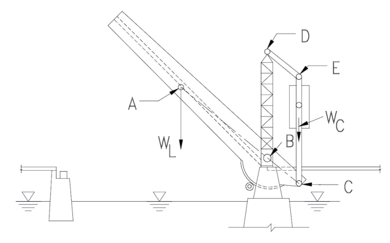
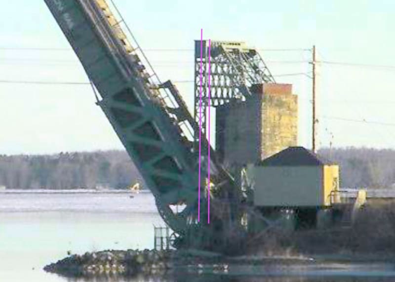
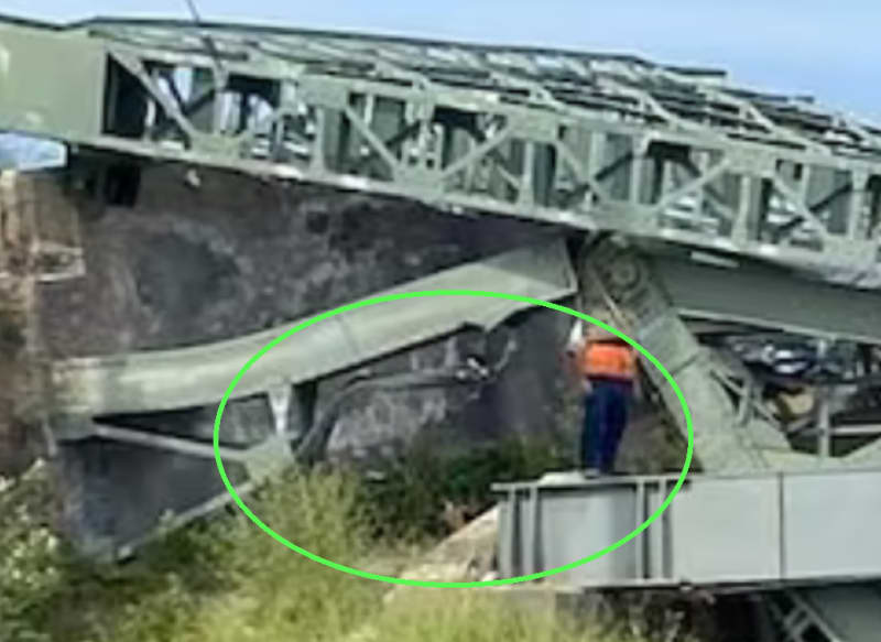
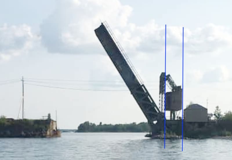
Ok in first image, if we can agree red arrow points to bottom of concrete counter weight, and blue arrows point to pit wall, then the only way I see the vertical contacted pit wall, was when the bridge was in the full upright orientation, such that the vertical could contact pit wall as counterweight fell or lost balance while bridge is in up position.

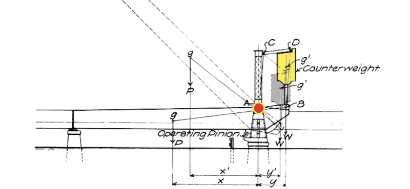
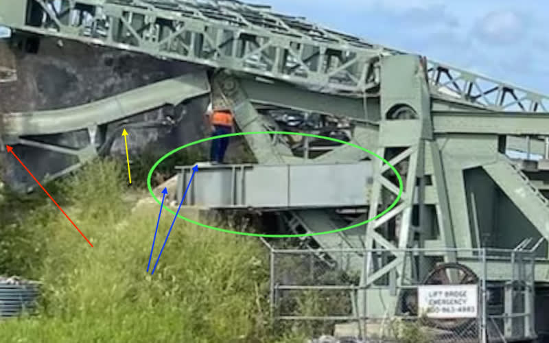
Problem is the bend in the counterweight support leg, is in the opposite direction from what you would expect. However, the damage to the diagonal is the bend damaged by pit wall. I will add new yellow arrow to the diagonal damaged by pit wall. Clearing the bending indicates the counterweight was moving towards the gantry to cause that bend.... If that is case, that indicates perhaps the other vertical has lost it's foot, thus the bent vertical bends under load re-distribution before falling backwards. And yes the bent vertical would contact the inside of the pit wall on the way up and down.

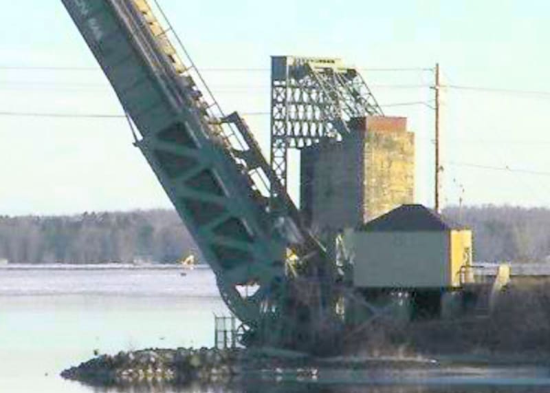
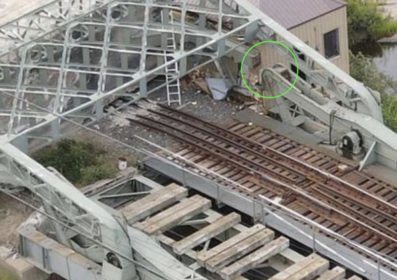
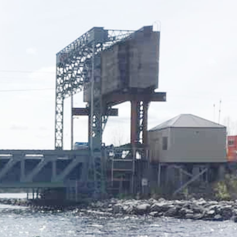
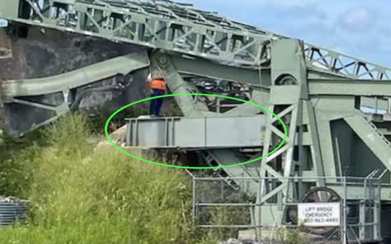
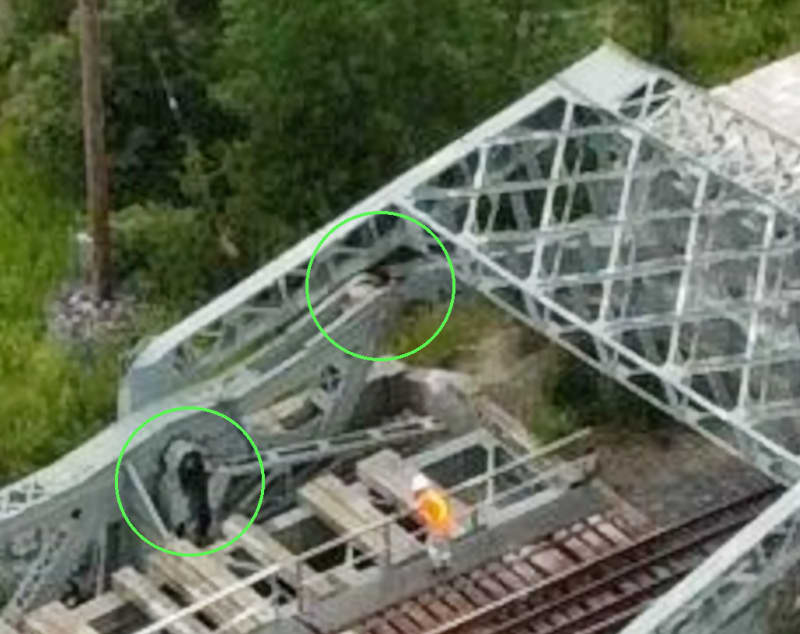
If that is the case, that confirms Symple's conclusion that bridge was in upright condition, perhaps in static condition before failure. The damage counter weight joint at leaf circled in 2nd image below, looks like partial failure also and/or signs of decay. Symple's second image also shows concrete damage on inside of pit wall.

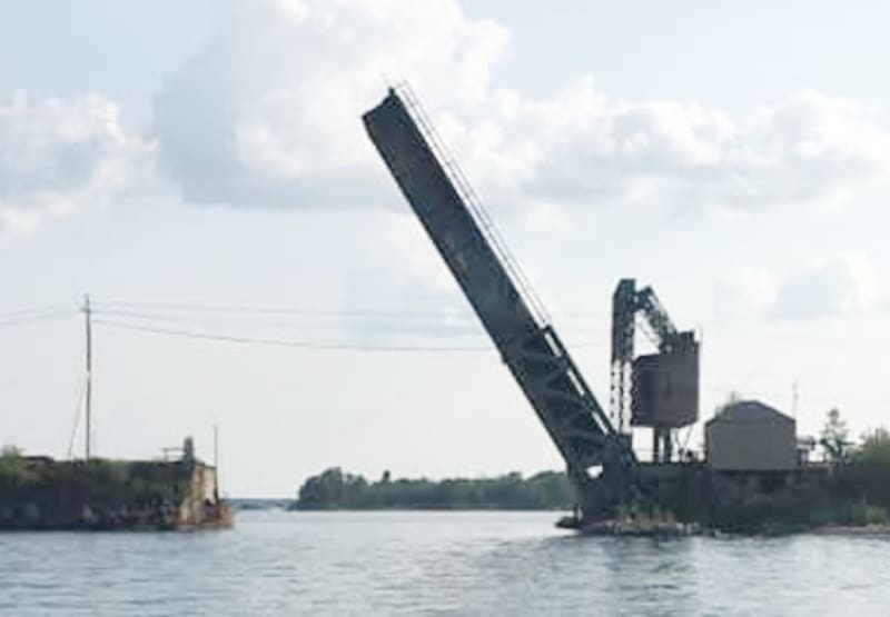
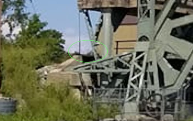
I have another image I will offer later from other side, that agrees with argument above...

Modern_Steel_e7zjpp_zgu1vz_px4kzn.jpg


bearings_wbyyrg_zv9y35.jpg
 
Camera image may be playing tricks in this image, as I added some lines. One is parallel to what I think is back of gantry, and the other back of counter weight....

From_Rainy_Lake_boats_q2jlp0_galc13.jpg
 
Status
Not open for further replies.
Back
Top