AK4S
Structural
- Jan 2, 2015
- 98
I am working on the connection detail of a Guardrail system and not able to figure out how a commonly seen system works!
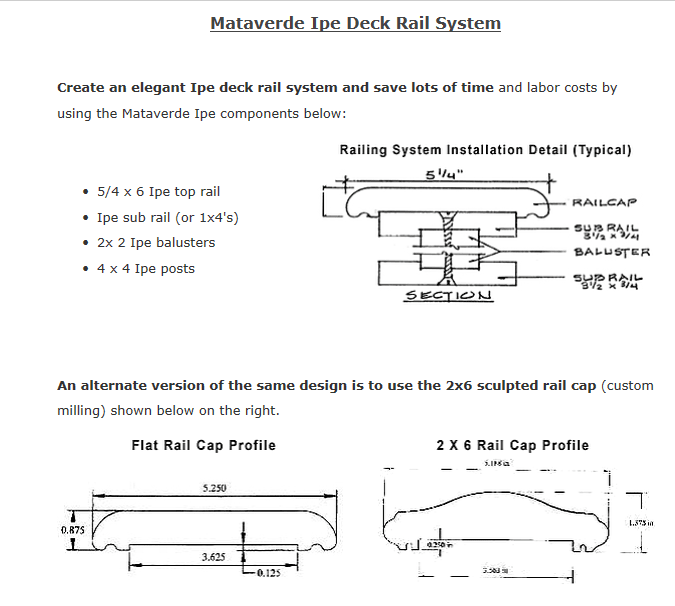
Railing system: Aluminium post with IPE top rail (no other sub rail).
This appears to be a common system as I could find several fabricators online (See attachment for photos)
Looking at the Connection between the IPE rail and the post:
The connecting screws would see: (1)Shear force at the interface (lateral load at the top rail)
(2) Tension/uplift when the Top rail sees a vertical downward load in the span and the ends want to rotate about the support at the cap plate.
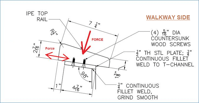
(Note: sketch above shows a T-shaped post. I am using a tube)
Question:
[ol 1]
[li]Will the connection screws actually see a tensile force?[/li]
[/ol]
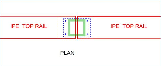
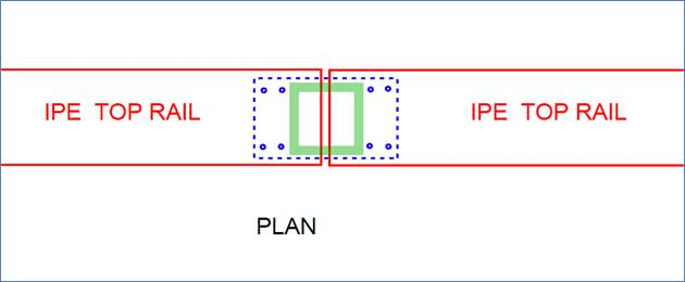
There are two scenarios: (A) the IPE top rail is continuous over the support (B) When two adjacent rail sections would terminate at a post as shown in the plan sketch above (either 2 or 4 screws on each side).
Logically I feel if the IPE rail rotates about the post cap plate, then the screws should see a tensile force, since they are resisting this rotation. But if I use this logic, then the tension on inner set of screws = moment/(distance from edge of cap plate to c/l of inner set of screws). This will be huge.
2. Can I detail it in some fashion which will make it behave purely as a pin at the support and the screws are resisting only shear forces from the lateral load. The photos from the attachment show only small screws, but I could not find any reference for their design.
Railing system: Aluminium post with IPE top rail (no other sub rail).
This appears to be a common system as I could find several fabricators online (See attachment for photos)
Looking at the Connection between the IPE rail and the post:
The connecting screws would see: (1)Shear force at the interface (lateral load at the top rail)
(2) Tension/uplift when the Top rail sees a vertical downward load in the span and the ends want to rotate about the support at the cap plate.
(Note: sketch above shows a T-shaped post. I am using a tube)
Question:
[ol 1]
[li]Will the connection screws actually see a tensile force?[/li]
[/ol]
There are two scenarios: (A) the IPE top rail is continuous over the support (B) When two adjacent rail sections would terminate at a post as shown in the plan sketch above (either 2 or 4 screws on each side).
Logically I feel if the IPE rail rotates about the post cap plate, then the screws should see a tensile force, since they are resisting this rotation. But if I use this logic, then the tension on inner set of screws = moment/(distance from edge of cap plate to c/l of inner set of screws). This will be huge.
2. Can I detail it in some fashion which will make it behave purely as a pin at the support and the screws are resisting only shear forces from the lateral load. The photos from the attachment show only small screws, but I could not find any reference for their design.