jcmrlec
Mechanical
- Sep 14, 2017
- 27
Hi guys,
Really struggling with something at the moment. We are designing some transport arrangements for an air transportable cabin. I have tried to attach a pic twice - hopefully it shows up.
We have two strapping scenarios that we are measuring strap tension using a load cell, one for a case and one for an ECU. Basically we have the case where one strap goes over the whole thing and the ECU where the straps hook to the corners ie the ECU has two straps. The problem we have is for some reason we can only measure roughly half the tension in the strap for the case, compared to the ECU straps. I have cranked the ratchet as hard as I can on both scenarios. For the case, i have tried putting the load cell in position 1 2 and 3 and all get pretty much the same result. To provide some numbers if i do the straps to a reasonable amount I get 200kg on the ECU and 100kg on the case. If I really try hard i can get 260kg on the ECU and 130kg on the case.
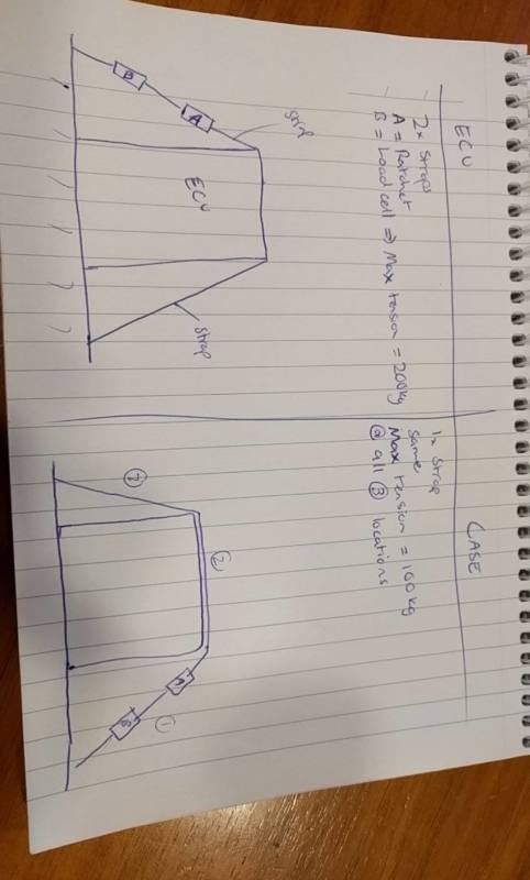
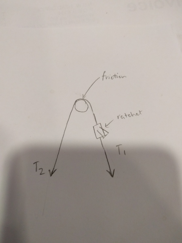
For the case, it should be pretty much just a pulley. So you should get the normal force on the case will be twice the measured tension in the strap (have allowed for angle but its pretty much vertical so can ignore it). But I dont see why the tension in the strap should change. There will be friction losses between the strap and case. But I think in the situation where the load cell and the ratchet are on the same side of the case that friction wouldn't affect it. I would expect to get less when the load cell is on the opposite side but this only changed it by about 10kg.
I think its too convenient that its halved. Also the case kind of deforms a bit. but i have tried cranking it more and i cant. Load cell is reasonably new and calibrated but again that shouldn't matter.
I have showed a few other Mech engineers at my firm and we are all confused. The only thing we can think is a combination of the strap friction, the case deforming and the extra strap wound on the ratchet (bigger lever to actually crank the ratchet) all contribute and its just a fluke that its half. It is making us feel stupid!
Hope someone can help.
Cheers
Really struggling with something at the moment. We are designing some transport arrangements for an air transportable cabin. I have tried to attach a pic twice - hopefully it shows up.
We have two strapping scenarios that we are measuring strap tension using a load cell, one for a case and one for an ECU. Basically we have the case where one strap goes over the whole thing and the ECU where the straps hook to the corners ie the ECU has two straps. The problem we have is for some reason we can only measure roughly half the tension in the strap for the case, compared to the ECU straps. I have cranked the ratchet as hard as I can on both scenarios. For the case, i have tried putting the load cell in position 1 2 and 3 and all get pretty much the same result. To provide some numbers if i do the straps to a reasonable amount I get 200kg on the ECU and 100kg on the case. If I really try hard i can get 260kg on the ECU and 130kg on the case.
For the case, it should be pretty much just a pulley. So you should get the normal force on the case will be twice the measured tension in the strap (have allowed for angle but its pretty much vertical so can ignore it). But I dont see why the tension in the strap should change. There will be friction losses between the strap and case. But I think in the situation where the load cell and the ratchet are on the same side of the case that friction wouldn't affect it. I would expect to get less when the load cell is on the opposite side but this only changed it by about 10kg.
I think its too convenient that its halved. Also the case kind of deforms a bit. but i have tried cranking it more and i cant. Load cell is reasonably new and calibrated but again that shouldn't matter.
I have showed a few other Mech engineers at my firm and we are all confused. The only thing we can think is a combination of the strap friction, the case deforming and the extra strap wound on the ratchet (bigger lever to actually crank the ratchet) all contribute and its just a fluke that its half. It is making us feel stupid!
Hope someone can help.
Cheers
![[sad]](/data/assets/smilies/sad.gif "[sad] [sad]")
![[bigsmile]](/data/assets/smilies/bigsmile.gif "[bigsmile] [bigsmile]") I don't think you're pranking us, but holy smokes, if you started this thread as a joke, it was a masterful display.
I don't think you're pranking us, but holy smokes, if you started this thread as a joke, it was a masterful display.