Continue to Site

Eng-Tips is the largest engineering community on the Internet

Intelligent Work Forums for Engineering Professionals

  • Congratulations KootK on being selected by the Eng-Tips community for having the most helpful posts in the forums last week. Way to Go!

RC hanging beam reinforcement at beam-beam connection 3

Status
Not open for further replies.

mr.rob

Structural
Jul 17, 2024
8
HI all,
Long time reader, first time poster here. [glasses]
I have a beam-to-beam connection with large shear forces. This is in Canada to A23.3. Hanging stirrups in the girder are too closely spaced to fit in the 'hanging zone' because only 2 legs out of 6 would be effective.
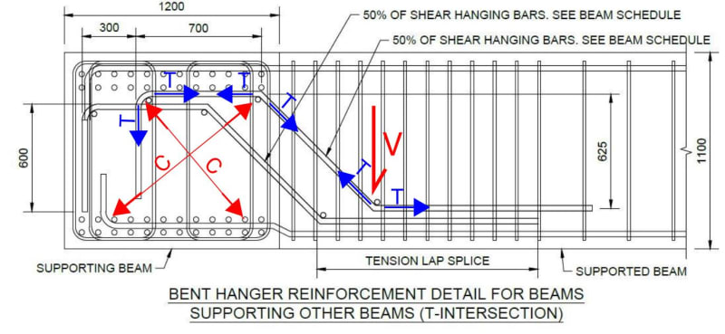
My proposal is to add inclined bars to carry the shear force "up" into the girder so that all 6 legs of stirrups are effective. Any and all feedback would be greatly appreciated.
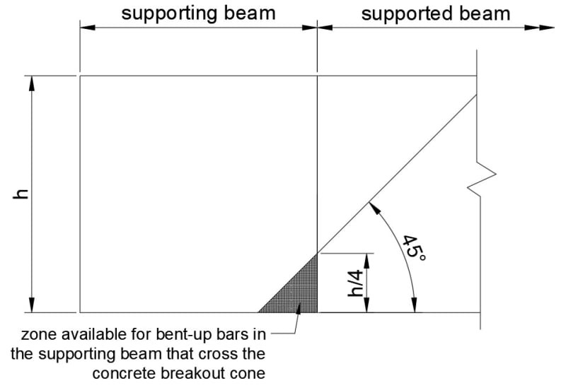
Capture1_avnx4v.jpg

Capture2_dcewvx.jpg
 
Replies continue below

Recommended for you

Welcome to the group, mr.rob. Those are pretty substantial beams. I like the idea of using bent up bars. It reminds me of the time when they were used in all beams.
 
Thank you BAretired!
This is for a transfer floor of a mid-rise. The floor plan gives no favours to structural layout. The supported beam is carrying a loadbearing wall and the supporting beam is carrying this load to the columns.
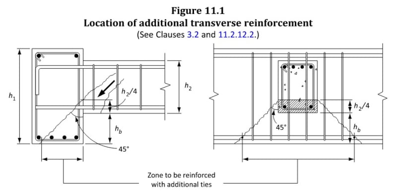
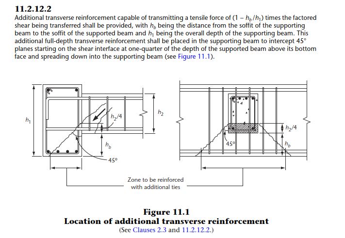
The intent is specifically to address the 'additional transverse reinforcement' in the supporting beam in accordance is A23.3-14 11.2.12.2. (a.k.a. hanging beam reinforcement)
Screenshot_2024-07-17_185408_a9lij7.jpg

I am aware of the use of bent-up bars to address regular one-way shear in lieu of stirrups. I have not been able to find any examples on the use of bent bars to specifically address the beam-to-beam connection the way I am proposing. The design guides concentrate on addition of stirrups in the supporting beam as per image above, which is not practical in my case.
 
Can you make the loadbearing wall do the work? Just suggesting...maybe the wall is not all across.
 
Hi hokie66,
No, not possible. The loadbearing wall is not all the way across and is of steel stud (CFS) construction.
It is also not possible to make the supporting beam deeper due to clearance constraints.
 
I’m in the US and am not familiar with the Canadian Code. That said, I think I understand what you are concerned about. There are 6 stirrup legs in the girder. You have determined that only two will be effective at the beam-to-girder connection. Does the Canadian code address this issue? (It is one that I’ve often thought about.) What are the variables that influence how many legs are effective? I normally add more stirrups in the girder at the beam connection (closer spacing and/or more legs) so that my beam shear reinforcing essentially extends into the girder. Can you do that – or are you already maxed out with your girder shear reinforcing? Can you add more legs of shear stirrups in the girder at the connection? Can you make the beam wider in order to better distribute the load to the girder? Can you use bigger size stirrups? I would also consider adding straight shear friction bars at the girder connection. It seems like they are needed but I’m not sure how to put a number on the strength they would provide. I’d classify them as “feel good” bars.
 
mr.rob said:
My proposal is to add inclined bars to carry the shear force "up" into the girder so that all 6 legs of stirrups are effective.

I guess I don't really see how this works mechanically. Does adding inclined bars fundamentally change the shear breakout cone such that the stirrup legs on the far end of the girder become effective? I can't visualize how this would be true.

I can see the inclined bars being effective in a shear friction type of mechanism, as long as the hooked end can provide reliable anchorage capacity across the shear plane. But I don't see that the far side stirrup legs would be activated in any way.
 
Hi cliff234 and bones206,
Canadian guide considers stirrups crossing a line drawn at 45 degrees starting from the bottom 1/4 of supported beam. You can see this visually shown on the left image in my 2nd post. When the beams are the same depth, only closest stirrup legs are effective. Adding more legs is not practical for the loads considering spacing and rebar congestion. Making the supporting beam wider is helping only marginally and does not seem to be a good trade-off for the increase in beam size.

The inclined bars are intended to carry the shear 'up' higher into the girder so that all the stirrup legs are effective. I marked this up below for one of the diagonal bars. These bars would be almost perpendicular to the crack shown on the left image of my 2nd post.
Capture1_mark-up_flk2xt.jpg
 
mr.rob, welcome to the forum. I think your approach is sound. Perhaps your compatriot KootK will chime in at some point. He and BA have a grip on all things Canadian.
 
I agree with bones.
The diagonals do carry the shear up, but so do the regular stirrups. If they did not carry the load up, the traditional truss model would not be valid. Regarding the crack shown in your earlier post I do not see how outer stirrups of the supporting beam can ever stop it from opening.
 
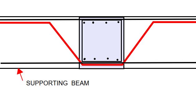
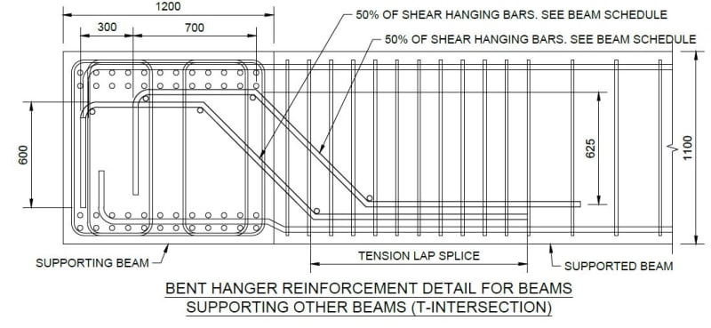
I would consider using bent bars as shown below in the supporting beam in addition to the bent bars in the supported beam. It avoids a clutter of stirrups and engages more of the supported beam in the intersection of the two beams.

Capture_ythpeg.jpg
 
Hi hardbutmild,

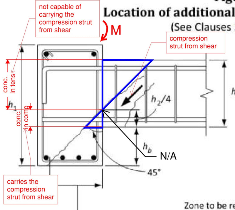
This is how I interpret it...
There is an end moment in the supported beam that puts top portion of the beam in tension. I am thinking this is the reason that the compression strut is shown to go through the bottom 1/4 of the supported beam, since concrete in tension cannot carry the compression strut. A vertical bending crack at the top portion of the beam near the interface could form that would effectively bypass the stirrups in the supported beam. The crack would also negate and friction resistance along that interface. If this scenario forms, the only bars that effectively cross the breakout cone are those in the supporting beam closest to the beam-beam interface.

Screenshot_2024-07-19_113328_wvwb10.jpg

Screenshot_2024-07-19_113301_v8k9v8.jpg
 
Hi BAretired,
I also thought about the bent bars in the supporting beam as you propose. The reason I went for the other approach, is that due to the beams being the same depth, the area crossed by the 45 degree concrete breakout line is too small to to fit those bars. If I am correct in my interpretation of the intent in the design manual, I think they would need to be in that zone to be effective.
Screenshot_2024-07-19_115606_r5tlti.jpg
 
Thank you hokie66! I appreciate the feedback.
 
A23.3 Clause 11.2.12.2 is repeated in full below. I can't quarrel with your interpretation, but when the beams are flush, hb is zero, so the full factored shear must be resisted within the small triangle in your last sketch. For the Tee intersection, i.e. exterior supporting beam, there is very little space to place all the stirrups.

I am still thinking about it, but one or two large diameter bent bars appear a better option than a forest of stirrups crammed tightly together. Or perhaps a combination of bent bars and stirrups. Tricky detail, for sure.

Capture_wtu3nh.jpg
 
In a connection like that, I like to put a few large bar dowels middepth. Not 'shear friction' bars, of which theory I am not an advocate, but big bearing dowel bars.
 
I don't love it.

1) This was a popular method to move shear around in the old days. I don't doubt that is effective to some degree but, as far as I know, there has never been a robust mechanism for checking it. Do the struts crush in the bar bend? Where does the tension go where the bars terminate? It's always been a setup that suggests strut and tie checking but never seems to actually get it.

2) Because of #1, I feel that using bent bars in combination with hanger reinforcement is especially problematic. From my perspective, it is adding an unquantifiable shear capacity (the bent bars) to a quantifiable one (the hanger bars). Something unknown + Something known = something bigger that is still unknown. Ick.
 
Would making the supported beam shallower and wider help here?
 
bones206 said:
Would making the supported beam shallower and wider help here?

It would in as much as this hanger steel connection provision is concerned. Obviously, that might tend to reduce the efficiency of the supported beam. Perhaps that's a worthwhile tradeoff.

The hanger steel methodology will most reward designers for having girders that are deeper than the beams that they carry. That's definitely a better condition as far as structural performance goes. It just runs counter to the economic benefit of having a common soffit elevation for all members.
 
When a beam is supported by a column, we don't worry about beam shear inside the column area. In fact, we don't worry about beam shear for a distance 'd' beyond the face of column.

I consider large bent bars in the carrying beam, not as shear reinforcement, but as a trapeze designed to transfer the reaction from bottom to top of the carrying beam. A23.3 requires us to carry the full reaction with steel, i.e. Vc = 0.

It could be done with large vertical bars, but they would need to be anchored top and bottom to develop the full reaction of the carried beam.
 
Status
Not open for further replies.

Part and Inventory Search

Sponsor