HI all,
Long time reader, first time poster here.![[glasses]](/data/assets/smilies/glasses.gif "[glasses] [glasses]")
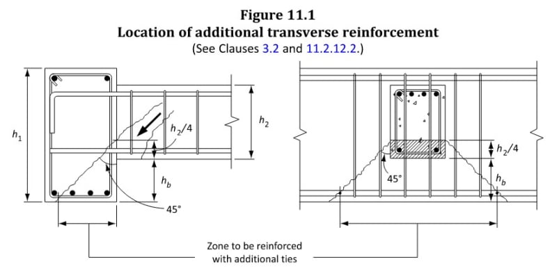
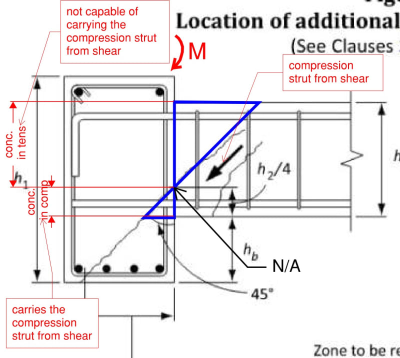
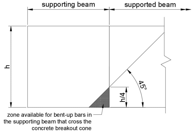
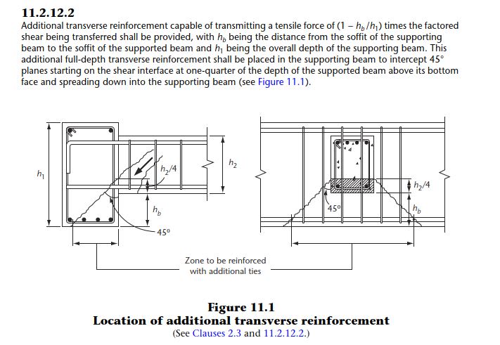
I have a beam-to-beam connection with large shear forces. This is in Canada to A23.3. Hanging stirrups in the girder are too closely spaced to fit in the 'hanging zone' because only 2 legs out of 6 would be effective.
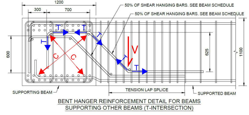
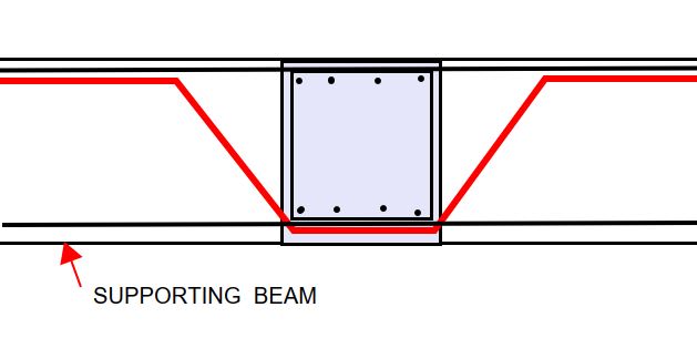
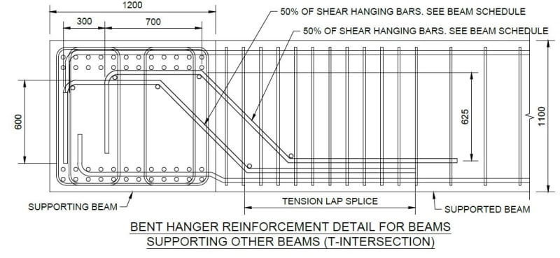
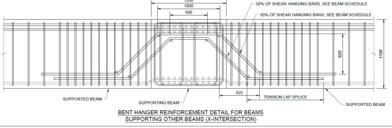
My proposal is to add inclined bars to carry the shear force "up" into the girder so that all 6 legs of stirrups are effective. Any and all feedback would be greatly appreciated.
Long time reader, first time poster here.
I have a beam-to-beam connection with large shear forces. This is in Canada to A23.3. Hanging stirrups in the girder are too closely spaced to fit in the 'hanging zone' because only 2 legs out of 6 would be effective.
My proposal is to add inclined bars to carry the shear force "up" into the girder so that all 6 legs of stirrups are effective. Any and all feedback would be greatly appreciated.