Eng-Tips is the largest engineering community on the Internet

Intelligent Work Forums for Engineering Professionals

RC Transmitter - Variable type possible???

Status
Not open for further replies.

zoo123

Mechanical
Aug 29, 2004
18
0
0
IN

Greetings all,
I am working on a simulation work environment, using Frugal and cheap resources and with 10 RC Toy cars of china make.

could not resolve the interference problem in the RC FREQUENCY. All are in 27mhz only.

But, i see in the Tx and Rx a variable screw type of inductor.

Can i use it to change the Transmitter frequency and accordingly retune in the Receiver board fitted in the car.

I just added the tx picture for ref. Look forward to your expert ideas friends.
Thanks
R.Babu
 
Replies continue below

Recommended for you

It's doubtful you'll be able to change the frequencies enough that they won't still interfere with each other. You need some form of multi-channel system (either via multiple frequencies or some form of code-multiplexing system).

Dan - Owner
Footwell%20Animation%20Tiny.gif
 

Thanks for the quick reply. But, ideally would that work out. Do agree an accurate solution. What you believe are going to add to the interference still.

Is the variable tower type(6 to7 mm height coil with a screw) inductor in the board , the right candidate for this job. still do you see any technical hiccups.


Thanks.

I am planning to vary the frequencies. Did a search of the chinese manufacturers of rotary variable inductor coils and asked them the sensitivity in terms of Frequency per turn. Will they respond me ???? [ponder]

Meanwhile, the inductor is so small, i have to be careful to turn it. I SEEK 9 VARIETIES OF Frequencies to be set in the Transmitter and correspondingly ensure i get the same in the receiver.

This being a 2 turn coil ( 720deg), i plan to turn it by max 60 to 80 deg. and check if there is a corresponding pick at the receiver.
my action plan
First Car => 0 deg.
Second Car => 60-80Deg
Third Car => 120-140deg
Fourth Car=> 180-200deg
And so on till ninth car.

i do not have a measuring instrument or Scope with me.

Pl. say if i am going on the right direction, Crude though.

 
"...variable screw type of inductor... ...27 MHz..."

I'm assuming that the transmitters and receivers are not crystal controlled. It's quite common that they are (you should recheck). Even with crystals, the circuit would still have adjustable components for alignment and peaking.

On this assumption: It's probably straightforward to retune the transmitters, but you should really use a frequency counter to do so. I'm not familiar with the 27 MHz frequency allocations in (ITU Radio) Region 3 (SE Asia), but with very low power it's probably (?) not critical to stay on exact channels. You should certainly stay within the band.

What's not necessarily straightforward is accounting for the receivers' bandwidth. It's likely that they're fairly broad and may respond to signals that are not widely spaced.

You may also run out of adjustment.

As Bill mentioned above, give it a try. We're just guessing here.

 
27 MHz? Forget it. That band is so polluted with CB radios, babyphones, garage remotes etc. It's like harpooning a fish in a mud bath.


All,

My sincere thanks for your views. Still trying. There is a 2.5 turn variable inductor prior to the antenna in this RC TOY CAR Transmitter.

I used a flat screw driver( a tiny one) and tuned it a bit crudely. I then checked if the car is responding to the forward , reverse, left and right , by pressing the tactile switch in the transmitter. Nothing responded.

I crudely retuned this variable inductor ( the screw seems to be made of ferrite core??). Then i repressed the tactile switches in the Tx randomly. I now saw the car responding.

I am not sure what is happening. me being not an electronic engineer could not understand what is happening when the ferrite core is turning.

I googled and i saw the word " Impedance matching" when the variable inductor is tuned.

Can any one help me know will the frequency of the transmitter change when the variable inductor is adjusted. OR WILL the frequency is same but something else is changing based on the impedance matching indicated ??. Thanks
 
You broke the transmitter so the receiver couldn't hear it, or couldn't understand it.
Then you sort of unbroke it.

It doesn't really matter whether you changed the frequency or the output power or something else entirely.

You need to read a book.

I recommend this one to get started:

It won't directly answer your questions, but it may lead you to the right questions to ask.

The book title suggests that you don't need an engineering degree, but you do need _some_ math and some physics to understand the material.


Mike Halloran
Pembroke Pines, FL, USA
 
OP said:
...variable inductor prior to the antenna in this....Transmitter.

Transmitters usually have their frequency-determining components at the opposite end (in terms of circuit signal flow) from the antenna.

If you find a variable inductor near (in terms of circuit signal flow) the antenna, then it's almost certainly an antenna matching or band-pass filtering circuit that would have essentially zero effect on the frequency.


Greetings,

I was reviewing with a chinese toy manufacturer today and she said, 2.4GHZ rc TOY Cars do not have interference and i can buy them as much as i want rather than going for a diff. frequencies. Not sure , how it is possible. Google search also indicates the same. Want to share and bring it to this group for your views . Sorry if I am changing topic.
 
Dear friends,
I wish to share some good news that i was able to iteratively vary the frequencies in the 4 RC Cars by varying the variable frequency transformer. And I succeeded decently. They are not interfering now. But, when they are very near there is a few cars interfere. But, i am happy to note something working now.

i Understood more on what is happening in these chinese cars that have been built for 27meghz.
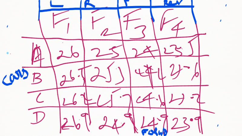
The 4 channels operate in diff. frequencies ( L, R, F, R). Since each has a set freq. thr. the circuit design with SMD Components.
The freq. transformer upon varying . it varies this set of 4 frequencies already set.
A meticulous variation gives a stable change and that is not repeated by the other one. When they are near to each other sometimes they interfere.
But, more than 4 for some reason, the frequencies are not changing and very tough to do it.
Note: I adviced an electronic person and he did it for me though and carried out what i wanted.

I had attached a sample template of frequencies for the four channels and a sample values ( tentative only not correct, since i do not have a Scope for this purpose.
car_frequencies_within27mhz_rvq9ah.jpg
 
Status
Not open for further replies.
Back
Top