Hi everyone,
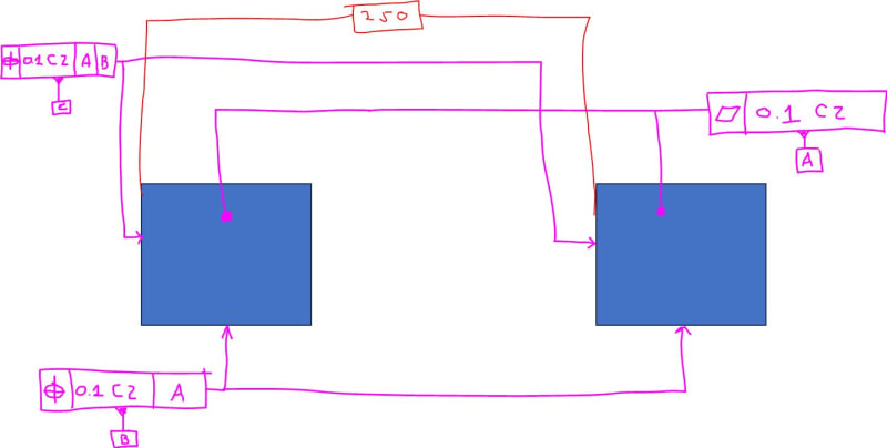
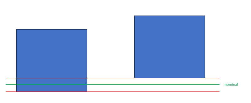
I would like to ask a question about creating a datum reference system. Me an my colleague were discussing whether the below is an appropriate GD&T notation. There are two 0-point pockets that are used to construct reference point system. It is part of a larger jig. Picture shown below. My question is, is the GD&T notation below correct? The idea is to create 3 planes from two pockets spaced 250mm or further apart. First a datum feature A is constructed by 2 planes. Then datum feature B which is perpendicular and defined as the combined zone of the two planes. And then the third plane which will be the mean plane between the two planes, so theoretically at 125mm. Is this the correct way to show this?
Thank you in advance for your answers.

Kind regards,
Kevin
I would like to ask a question about creating a datum reference system. Me an my colleague were discussing whether the below is an appropriate GD&T notation. There are two 0-point pockets that are used to construct reference point system. It is part of a larger jig. Picture shown below. My question is, is the GD&T notation below correct? The idea is to create 3 planes from two pockets spaced 250mm or further apart. First a datum feature A is constructed by 2 planes. Then datum feature B which is perpendicular and defined as the combined zone of the two planes. And then the third plane which will be the mean plane between the two planes, so theoretically at 125mm. Is this the correct way to show this?
Thank you in advance for your answers.

Kind regards,
Kevin


