Eng-Tips is the largest engineering community on the Internet

Intelligent Work Forums for Engineering Professionals

Reference Point System 1

Status
Not open for further replies.

Auxcron1

Aerospace
Sep 4, 2024
3
0
0
AT
Hi everyone,

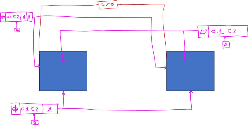
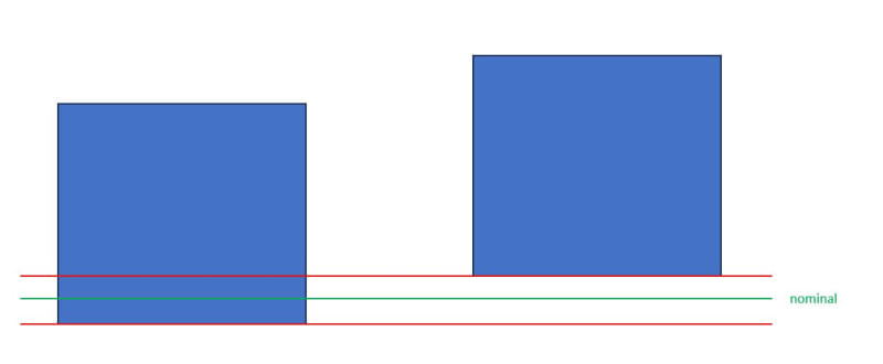
I would like to ask a question about creating a datum reference system. Me an my colleague were discussing whether the below is an appropriate GD&T notation. There are two 0-point pockets that are used to construct reference point system. It is part of a larger jig. Picture shown below. My question is, is the GD&T notation below correct? The idea is to create 3 planes from two pockets spaced 250mm or further apart. First a datum feature A is constructed by 2 planes. Then datum feature B which is perpendicular and defined as the combined zone of the two planes. And then the third plane which will be the mean plane between the two planes, so theoretically at 125mm. Is this the correct way to show this?

Thank you in advance for your answers.

GD_T_t1vus4.jpg


Kind regards,
Kevin
 
Replies continue below

Recommended for you

I don't see a problem with that, but I wonder if - functionally speaking - B and C have to be common tolerance zones. While B as a CZ could make some sense, I doubt that the C planes really require to make common contact.
 
My recommendations are:
- Specify the perpendicularity of B to A and C to A & B, instead of position. I don't think that the position tolerances have meaning until a 3-D, zero DoF datum frame is established (A, B and C).
- Specify the flatness of the 2 B surfaces together.
- Specify the C datum as only 1 surface, not 2, and add a flatness specification.

Best regards,
Doug Hunter
Altarium Technical Consulting

 
Germermaman

thanks a lot for your reply. I think CZ for datum feature C is still important as if the CZ was not there, bot surfaces would be treated independently. The position control as it is used in the picture is only controlling the orientation of the datum feature C, even though it is a position tolerance. If I removed CZ, one surface could be machined further to the right or to the left of the other one, which would depend on the general tolerances for the drawing. Both could still be perfectly oriented to datum features A and B but the distance between them could be bigger or smaller. That 250 dimension would not actually be controlled by any GD&T then. Please correct me if I am wrong but that is my understanding of CZ in this instance.

Doug Hunter
Thanks a lot for your suggestions.
- I was thinking of doing it this way but I think if I used perpendicularity instead of position tolerance, the following scenario could occur, correct me if I am wrong:
GD_T_2_rsar4p.jpg

The faces would be orientated to A correctly but their relative position would solely depend on the general tolerances defined in the drawing border.

- Isn't flatness already controlled by the position tolerance zone?

- Again, isn't flatness specified by the position tolerance zone as well? In this case, we need to use both surfaces to create a robust reference point system. In reality, that cube has about 20mm * 20mm. If we created a datum reference system from only 1 small area for a jig that is say 1m long, it could throw off measurement and introduce error on the other side of the jig.

Thanks both for your comments!
 
Kevin,
I don't think that the position tolerance will give you what you want. At the very least, I think that one part of B needs to be positioned relative to the other part of B. The perpendicularity, in conjunction with the flatness, would not allow that beyond the flatness limit. Also, the situation you are concerned with allowing with perpendicularity could still happen with position. I think that the flatness control of C would prevent the problem you are concerned with. Until your 3-D, zero DoF datum frame is established, I think your GD&T controls have to be for form.


Best regards,
Doug Hunter
Altarium Technical Consulting
 
Auxcron, it depends on the function as to whether your application of tolerances is correct/optimal, but what you've done is valid.

I believe the use of perpendicularity would have the same effect as position since the CZ modifier internally creates a location constraint for the pattern. That said, I'd personally stick with position because it's much better defined in ISO 5458 leaving less room for misinterpretation. When referencing pattern datums, the correct callout under ISO GPS is A-A, B-B, C-C, etc.

Ryan.
 
I don't think perpendicularity can be used with CZ. It's true that those surfaces are only related to the given datum(s) in a perpendicular manner, but the problem is that it's trying to also locate them to each other, which is something the perpendicularity symbol can't do.
In ASME the profile of a surface symbol would be the way to go, but since this is ISO then position on those surfaces might actually be best.
 
Garland23, this comes back to my point that position is less ambiguous because it's better defined. My initial thoughts were the same as yours - that is can't be applied to perpendicularity. But I re-read ISO 5458 to respond to the question and saw that CZ applies an internal constraint that controls both orientation & location. The perpendicularity control is then a separate external constraint. There's nothing in the standard excluding use of CZ on orientation controls. This ambiguity is the reason I suggested using position anyway.

Ryan.
 
Thanks a lot everyone,

Garland23 and Ryan6338
I used position tolerance for that very reason, I need to control their relative position as well which to my understanding, perpendicularity alone with CZ can't do. I always avoided using orientation control with CZ to control relative position as I do believe it is more ambiguous as well.

Doug Hunter
I do see your point about using flatness to control the relative position of those two surfaces and to be honest I think that in conjunction to perpendicularity, this would work for datum feature B. However, I think that position tolerance does the same thing as it controls the orientation as well as relative position of those 2 surfaces. They are constrained together using modifier CZ as not all degrees of freedom are locked while making B. So they do move together thanks to CZ modifier. And yes, the situation I described above could still happen, however, it will now only happen in the range of 0,1 positional tolerance which is what I want.

Many thanks again everyone, really appreciate your help.
 
I also believe that perpendicularity used with CZ for datum features B should be an allowable option. The fact that it would control relative location of the features in addition to the orientation to the datum plane A shouldn't be a concern, otherwise flatness with CZ shouldn't have been allowed too.

Technically, there is one more option on the table - surface profile, which basically indicates that this is sort of muddy area in ISO standards.

The original sketch does not show how (at what material condition) datum C is called out. One thing worth remembering here is that if it is, by any chance, called out without any material modifier (i.e., MMR or LMR), the rule in ISO is that the distance between the two associated planes used to establish the datum center plane C shall be basic, unless [DV], distance variable, modifier follows the datum letter.
 
pmarc said:
I also believe that perpendicularity used with CZ for datum features B should be an allowable option. The fact that it would control relative location of the features in addition to the orientation to the datum plane A shouldn't be a concern, otherwise flatness with CZ shouldn't have been allowed too.

Technically, there is one more option on the table - surface profile, which basically indicates that this is sort of muddy area in ISO standards.

The original sketch does not show how (at what material condition) datum C is called out. One thing worth remembering here is that if it is, by any chance, called out without any material modifier (i.e., MMR or LMR), the rule in ISO is that the distance between the two associated planes used to establish the datum center plane C shall be basic, unless [DV], distance variable, modifier follows the datum letter.


Interesting approach pmarc.
Speaking about ISO and my ignorance in understanding its full system, may I ask you why you could add MMR for datum C? Does it have a location relationship with its higher precedence datums?
I see them as a planar features, but you might be able to fix my missunderstandings :)

 
Again, just to clarify: I am not understanding how C(MMR) could be used, as C is not a feature of size (it lacks opposing and parallel elements) nor it has LOCATION relationship with B and A.
 
pmarc,

May I have a follow up question regarding ISO system: is the approach shown in figure 7-33/ ASME Y14.5-2018 available (valid) in ISO GPS?
I am asking if a feature is not a feature of size (linear size or angular size)--such a planar datum feature B-- could it be modified at MMR?
(in ASME I think it could, as shown in figure 7-33 because HAS a location relationship with primary A).
Has ISO GPS this approach available or not (to callout a planar datum feature at MMR or LMR)?
Would the ISO callouts look identical -the same --in ISO?

Thank you pmarc


QFM_-_Copy_cy4jph.jpg
 
Pmarc, I claimed that perpendicularity can't be used to locate multiple surfaces to each other based on the idea that perpendicularity can't be used on a group of holes to locate them to each other (like composite position would).
But I see your point that flatness CZ could logically extend to perp CZ.
 
Garland23

Garland23 said:
I claimed that perpendicularity can't be used to locate multiple surfaces to each other based on the idea that perpendicularity can't be used on a group of holes to locate them to each other (like composite position would).But I see your point that flatness CZ could logically extend to perp CZ.

I think it is a subtle fact but, CZ, combined zone, does not locate/ orient features. It does locate / orient the tolerance zones. Where CZ is indicated in tolerance indicator all the related individual tolerance zones shall be constrained in location and in orientation amongst themselves using either explicit theoretically exact dimensions (TED), or implicit TEDs.
 
Pmarc,
So if what's showing in fig 7-33 is truly design requirements then how would you say it in ISO?
Maybe with a lengthy note and not with symbology? [pre][/pre]
 
greenimi said:
I think it is a subtle fact but, CZ, combined zone, does not locate/ orient features. It does locate / orient the tolerance zones. Where CZ is indicated in tolerance indicator all the related individual tolerance zones shall be constrained in location and in orientation amongst themselves using either explicit theoretically exact dimensions (TED), or implicit TEDs.

However, based on that do you think ISO should allow perp with CZ to be used on a pattern of holes? As you say, it would constrain the perp tolerance zones for orientation and location. By doing that it could replace position (assuming that it's positioning the holes among themselves, not to external edges).
But that sure doesn't sound right, to have perpendicularity take the role of the more powerful position symbol.
 
Garland23 said:
However, based on that do you think ISO should allow perp with CZ to be used on a pattern of holes? As you say, it would constrain the perp tolerance zones for orientation and location. By doing that it could replace position (assuming that it's positioning the holes among themselves, not to external edges).

So which statement from my above replay you are disagreeing with?
Could you, please point it out? I am confused now.

Just quote it (copy and paste) here, please


Status
Not open for further replies.
Back
Top