Eng-Tips is the largest engineering community on the Internet

Intelligent Work Forums for Engineering Professionals

Regenerative brake 3

Status
Not open for further replies.

Sajuuk

Industrial
Jul 13, 2020
2
0
0
FR
Hello,

I know some basics about electric motors (sync, async, DC) but i know nothing about regenerative braking used in some cars (e.g. hybrid or fully electric).

I read on wikipedia that it is not (yet) possible to completely and safely stop a vehicle only by using it and a manufacturer still needs brake pads.

Is it really the case ? Where can I find some research on this ?

Could it be possible with the right electronical system ?


Thanks for your answers :)
 
Replies continue below

Recommended for you

Bill, as far as the motor and inverter stage are concerned, you can develop as much braking torque as motoring torque. It's highly symmetrical. (And that's neglecting the help of friction losses in decelerating.)

I'm not an expert on batteries, as the systems I deal with regularly have capacitor banks. But I think most battery technologies have pretty similar charge and discharge rate limits. Right now I don't have the time to research this.

Curt Wilson
Omron Delta Tau
 
waross said:
Got it.
waross said:
The limit is not the motor but the ability of the electronics to inject the small regenerated voltage back into the batteries

No, you don't get it. Say the inverter uses 200W to run (fans, electronics etc). You can't get any regenerative energy to flow back TO the power source once the motor is turning so slowly that it is generating less than 200W. Energy can still be flowing from the motor to the inverter, but at the same time energy is flowing FROM the power source to the inverter.

waross said:
Lionel, your braking torque is dependent on the current and will hold up as long as the speed is above the slip RPM or frequency.

Might as well point out that this is wrong too. A good inverter can make an induction motor produce rated torque right down to ZERO speed and hold zero speed at rated torque.
 
Perusing a Tesla forum, I see that Tesla cars have a warning light that comes on at low outside temperatures, telling you that the regenerative braking capability is reduced. This is due to the reduction in charging rate of the battery at lower temperatures.
 
Could it be that there are multiple definitions talking past each other? It seems to me that there are at least a couple of strategies for “regenerative braking” that would harvest different amounts of energy and would have different braking characteristics.

The first would be to extract energy produced from the vehicle rolling faster than it’s being driven. Diminishing returns and all that.

The other, while probably not meeting a classical definition of regenerative braking developed over a hundred years ago, would be to actively extract energy. If the sole goal is doing as much braking electrically, and having a resistor grid for when the battery is full (classically referred to as dynamic braking) then a lot more braking can be accomplished.

So, maybe, if everybody could agree on what regenerative braking means, maybe some of the disagreement would resolve.
 
That agreement was made long ago. Regenerative braking only ever means using the motors as generators to produce a braking effect, and recharging the propulsion battery using the electricity produced.

Locomotives use resistor grids, and it's called "dynamic braking" in that application, because you are not regenerating anything.

In an automotive application, no one is going to use a resistor grid, because there are always mechanical brakes. Always.

Yes, locomotives in trains have mechanical brakes, too, but their thermal capacity is severely limited relative to the mass of what's being slowed down. If you use the mechanical brakes to control the descent of the train down a mountain, you will smoke them, and crash into whatever's at the bottom of the hill ...
 
Huge banks of metal strips that serve as load resistors in the top of the locomotive.
I was watching a train make a moderate decent once in the winter during a light snow, it was raining alongside the loco from the heat rising off of it.

I did see a clever one once at an open pit mine. The haul trucks are all diesel electric using wheel motors and no battery storage. The motors will take a 15% overload for a few minutes, so they added overhead lines and pantographs to the trucks and tied it all to the central power system. Trucks descending could not use regenerative braking and trucks climbing could run higher power. They could either speed up the operation or they could make the haul roads steeper and save excavation.

= = = = = = = = = = = = = = = = = = = =
P.E. Metallurgy, consulting work welcomed
 
When a train applies the braking resistors, how does one control the braking intensity, i.e., are there power transistors that switch in individual banks, or is it a one and done thing?

I seem to recall reading somewhere the entire set of resistors is switched onto the drive motor busses via contactor and braking degree is controlled by the amount of excitation applied to the motor fields.

CR

"As iron sharpens iron, so one person sharpens another." [Proverbs 27:17, NIV]
 
That might be the case for induction motors, but PM motors wouldn't have that. Nevertheless, I did run across mention of doing PWM on the resistors, which requires yet another switching device and control circuitry; that could easily allow for 100:1 control ratios. However, that does require a certain maximum current capability in both the regen and resistors to handle the maximum braking required.

TTFN (ta ta for now)
I can do absolutely anything. I'm an expert! faq731-376 forum1529 Entire Forum list
 
For many years locomotives used DC traction motors.
Many are now using induction motors.
The resistors are still mounted on top of the locomotive but the technology has changed.

Bill
--------------------
"Why not the best?"
Jimmy Carter
 
It was those older ones I was referring to, Bill.

IIRC there were two different sets of contactors for the fields, one of which was for reversing the drive direction and another that placed the series windings in series and applied regulated excitation to them for dynamic braking purposes. Some locos also included "transition levers" for re-configuring the series or parallel configuration of the armatures of the drive motors to accommodate different operating speed ranges.

CR

"As iron sharpens iron, so one person sharpens another." [Proverbs 27:17, NIV]
 
Wow, so much answers, thank you so much to all of you !!

So, to sum it up :

Regenerative breaking swallows up a great amount of energy in most of braking cases. Problems come when :

1 - Emergency breaking, where I would need a resistor to dissipate the huge amount of power the battery can't hold. A capacitor could help in that case, if I'm not mistaken.

2 - To stop the vehicle, I would need to consume some of the energy in my battery to lock the wheel, thus, decreasing the over-all efficiency of the regenerative system.

Am I right ?
 
And further to (2), the vehicle needs to stop and stay stopped when someone turns it off and walks away for a week, a month, a year, with the vehicle stopped on a slope. It can't require active power to maintain that situation because that active power will eventually run out. That needs a mechanical brake.
 
The term regenerative braking in general just means that you convert back mechanical energy back to electrical energy through the motor.

This already saves a lot of wear on a mechanical brake. In ideal case, you than feed back this energy back into the battery or the overhead line /third rail.

Nevertheless, as there might be conditions, where the battery or the line cannot accept energy fed back. For this condition there is usually a brake resistor provided.
 
It depends on your point of view and the definition you choose to apply to regeneration.
For a system to regenerate it must return energy to the source.
But what about a motor?
Case one.
An induction motor is regenerating into the batteries due to the supply frequency being lowered.
The batteries can no longer accept the energy and the energy from the motor is diverted to a resistor bank.
We have changed the name from regenerative to dynamic without any change in the action of the motor.
It is still producing and exporting energy.
Case two.
An induction motor is exporting energy that is being dissipated in a braking resistor. Dynamic braking?
Now the control system changes from under frequency braking to DC injection braking or the traditional dynamic braking.
The system has changed, the motor is no longer exporting energy, but the name is the same.
I need a new word to describe a motor exporting energy even when the system is not exporting energy.
That new word should probably be applied to locomotive braking as well.

When a motor is acting as a generator and exporting energy, does the motor know or care where that energy is going.


Bill
--------------------
"Why not the best?"
Jimmy Carter
 
Back to the practical application of motor braking of a vehicle,
There are some parallels with heavy truck retarding.
Heavy trucks often are fitted with engine brakes.
These are either compression release brakes (Jake Brakes) or exhaust brakes that restrict the exhaust flow.
They are retarders rather than brakes.
They are not the primary braking force, they act to assist the service brakes.
They only work when the vehicle is moving.
They will not bring a vehicle to a complete stop nor hold it stationary.


Bill
--------------------
"Why not the best?"
Jimmy Carter
 
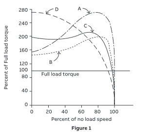
Braking torque characteristics of an induction motor used in an electric vehicle:
The first application is retarding on a long grade.
To avoid overheating the motor, the retarding torque and current will be thermally limited to rated full load torque and current.
The maximum short time braking will be limited by the breakdown torque of the motor.
The breakdown torque varies with the design of the motor.
image_bvumc9.png

This Figure from the Cowern Papers shows the torque curves of the standard design industrial induction motors.
The design B is the most common design with a breakdown torque of about 200% of rated torque.
The main factor in the torque curve of a motor is the rotor design.
The resistance of the squirrel cage as well as the shape and the distance below the surface of the rotor affect the curve.
The maximum or breakdown torque of a design a or design D industrial induction motor is about 280% of rated torque.
I have no idea of the design choices of the electric vehicle motors.
The braking energy of the motor drops as the speed drops, however the braking torque remains constant down to about two times the slip speed.


Bill
--------------------
"Why not the best?"
Jimmy Carter
 
Bill:

With an induction motor, any time you use negative slip (electrical frequency less than mechanical frequency), the motor becomes a generator. With a synchronous motor, any time you use a negative torque angle (electrical angle lagging mechanical angle), the motor becomes a generator.

So motor jocks consider the motor to be “regenerating” in all these cases, because this operation returns mechanical energy to electrical energy.

In the case of electric vehicles, we are controlling the motors from a DC bus through an inverter using “field-oriented” control. For induction motors, as with older Teslas, the FOC calculates the slip it applies as proportional to the torque it wants (of either sign). This limits the slip to the right-hand end of all of the torque curves you show, between the non-load torque and the breakdown torque.

In the industrial world, this regenerated electrical energy charges up the capacitor bank on the DC bus. Many times, this energy is then used to power the next acceleration (particularly in my world of positioning servo systems).

Virtually all industrial drives provide the capability to dissipate this energy through a “shunt” resistor, even if this is an external option. As far as equipment cost is concerned, this is the cheapest way of getting rid of excess regenerated energy.

You can buy a “regenerative drive” that can put the regenerated energy back into the AC mains. I would prefer to call these “line-regenerative drives” as a clearer name for what these drives do. These are more expensive, as they require a second full inverter stage, and its controls, to interface to the line.

I make the semantic point because a lot of people think you need one of these expensive drives to be able to apply braking torque at all, which simply is not true.

Curt Wilson
Omron Delta Tau
 
Status
Not open for further replies.
Back
Top