Continue to Site

Eng-Tips is the largest engineering community on the Internet

Intelligent Work Forums for Engineering Professionals

  • Congratulations KootK on being selected by the Eng-Tips community for having the most helpful posts in the forums last week. Way to Go!

Reinforcing a W section for Torsion. 3

Status
Not open for further replies.

Sweever

Structural
Sep 13, 2017
29
I have an existing W section that is loaded eccentrically, about 5" off the web centreline. There is no way to brace the flanges and take out the torsion and no easy way to remove the beam and replace with a HSS. We were thinking of installing a HSS section in the top right corner of the beam and welding it to the top flange and web of the beam to take the torsion. Anyone ever done this? If the W section can take the bending and shear, can one just design the HSS to take the torsion and provide a suitable connection at the column? Would there be issues with the section no longer being symmetric? Never really have done any torsional reinforcements before and typically stay away for torsional situations. Any comments would be appreciated.

Thanks
 
Replies continue below

Recommended for you

I know I might be 'beating a dead horse' here, but wouldn't it be better to have the small bending load on the columns due to the beam being supported eccentric to the column, rather than having torsion on the beam? Wouldn't it be simpler provide brackets at the columns to support the beam off-center than to modify the beam for torsional resistance?
 
Beating that dead horse a bit further I'd even consider a second offset beam to potentially be easier all round than trying to deal with the torsion, modification of end connections, moving a beam, etc. We don't know all the details of course, but I think if torsion is being relied on then the discussion of others has covered it adequately.
 
hotrod said:
If I'm not mistaken about the internal mechanics (although I could be mistaken), if only the W-beam is supported at the ends of the beam, then the eccentricity to the load remains from the centerline of the web

I believe that this is correct, at least for the end of the member, and is something that is commonly missed. At the supports, the shear center location is a function of only those parts of the cross section to which the reaction force is distributed. The classic example is that of a channel web connected to it's support. Is the shear center at the web or outside the web? At the end of the member where the reaction force is introduced, it's the former. Hotrod, feel free to correct me if I've not interpreted your position accurately.

TLHS said:
Koot, I agree but with an asterisk.

I'll take it! Based on the comments so far, and the star going to canwest's critique, I suspect this will be a long, loveless slog for me.

TLHS said:
A weld discontinuity shifts torsion into bending of individual elements where there's no weld (or field action, as per below).

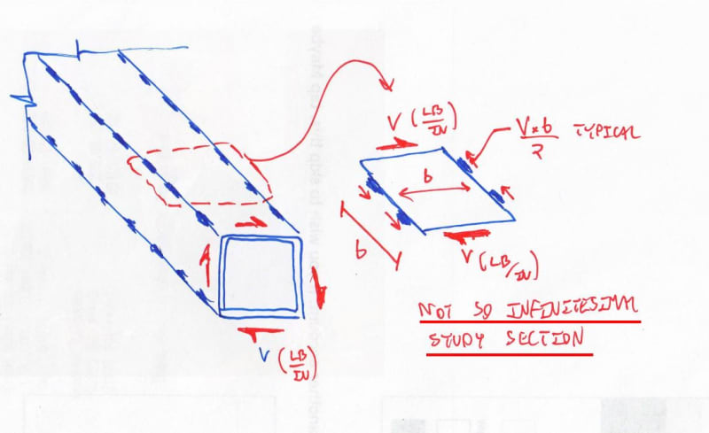
Meh. I absolutely agree that it changes the character of the shear field such that other things are going on but I'm not sure that I see bending as the predominant thing. It would be more tension/compression field under any reasonable weld spacing I think. See the sketch that I'll post in the comment after this one.

TLHS said:
You can physically try this yourself. Fold a piece of card into a box section and twist it. Now take a knife and cut the corners periodically. You're going to significantly increase flexibility and decrease capacity without load continuity.

This is an interesting analogy but is missing something important. The longitudinal dimension of the tube will much greater than the transverse dimension. This means that you've got miles of stitch weld available to resist the shear floor associated with St.Venant shear flow on the cross section. This isn't true of your box unless it's a very unusually proportioned box.

TLHS said:
Once I'm doing that, it's honestly probably faster and cheaper to just lay down a quarter inch weld.

TLHS said:
You only really need to worry about combination of tension/compression due to bending and shear due to torsion when you're high in the stress ranges.

For me, the bigger worry would be warping torsion axial stresses developing in the flanges and combining with bending axial stresses. This is a big part of why I recommended a tube with enough torsional stiffness that it could realistically be expected to shield the WF from picking up torsional load.

canwesteng said:
I can buy the space truss analogy for torsional stiffness, but it seems awfully complicated to check.

TLHS said:
Once I'm doing that, it's honestly probably faster and cheaper to just lay down a quarter inch weld.

With love, gentlemen, I think that you're making mountains out of mole hills with this. If I'm doing it it's:

1) Check against Tc/Jt or whatever to get first minimum for welding.
2) Check that weld spacing is less than 2x diaphragm plate width as I mentioned above.

The end. No big outlay of time or metal energy. While the argument doesn't seem to have garnered much traction, I still content that a) this is almost completely analogous to our usual VQ/It voodo and b) that's an important insight. In a flexural reinforcement, it's not just axial load being resisted. Rather, it's a gradually varying axial load. And that's significant because it means that you have to pick up shear in the beam as you go and, by the book, that's not possible in the Bernoulli sense between welds. But still we do it and, clearly, it works. Same deal +/-.
 
hokie66 said:
Torsional closed sections need to be closed along the complete length.

hokie66 said:
Cut a side out of the CLOSED section at any point, and the shear has nowhere to go.

I vigorously disagree with both of these statements. The sketch below illustrates the mechanics of where the shear would go in the stitch welding case. There are places for the load to go when you cut out a chunk of side as well, those places are just flexible to a neutering degree.

hokie66 said:
Most would agree that a flexural cover plate cannot have discontinuities, neither can a torsion bar.

A stitch welded cover plate does have similar discontinuities. They are the stitch welds and the fact that, as I mentioned in the previous post, the stitch weld make it such that shear cannot be added to the beam in a Bernoulli sense between stitch welds.

hokie66 said:
Torsion is shear, and the shear resistance cannot be interrupted.

The load transfer between a beam and it's cover plate is also shear. And it obviously can be interrupted. I see this as a rather salient counter example.

c01_fulpc3.jpg
 
No traction, no agreement, at least with me. I think TLHS's analogy is appropriate.

By discontinuity of a cover plate, I meant a gap in the plate itself, not in the welds.
 
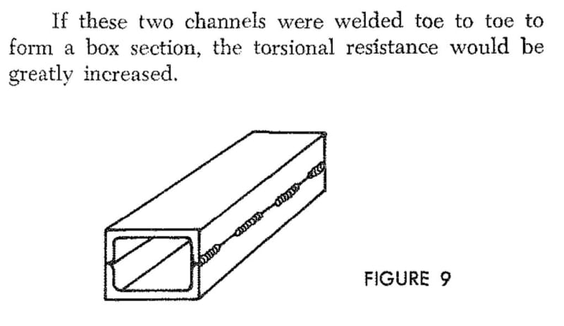
Would you be willing to put more stock in Omer Blodgett's assement?

c01_fooocx.jpg
 
Just to clarify, I think a stitch weld is likely completely reasonable within the normal limits of element width to thickness ratios and stitch spacings that a reasonable engineer would pick for something like this. There is just definitely a bending/buckling/compression failure (depending on whether you want a bending or truss analogy between the welds) limit state in there that one has to keep in mind. The folded card example demonstrates an extreme, but I think is valid in demonstrating the overall effects that you'd see. Note that if you make very small perforations, you would end up with a pretty stiff and stable structure as well. It's not something I'm overly worried about, but there's some limit there and I'm curious about the limit state.

I'm pretty sure I could draw up a pretty good truss analogy that I could use to verify design if I really needed to. I'm also confident that stiffness is affected, but the extent of that effect depends on the spacing of welds and properties of the plates. For reasonable stitch distances it might be small enough to ignore, but if you're really deflection sensitive on something it could add up over a distance.

Note that you can totally build up a box section using nails, rivets or bolts that has increased torsional strength. You can also make a space frame truss box section that has increased torsional properties. You don't need that continuous connection.

Also of note for people saying it's absolutely necessary, Blodgett specifies a stitch weld on a closed box section used for torsional resistance on page 2.10-24 of 'Design of Welded Structures'

I honestly just wouldn't worry about this when I'm doing design and would use a small weld along the whole length. However, on the occasions where I deal with torsion using closed sections, the loads are normally high enough that I'd need a continuous weld anyway or it's an installation that I need sealed. So I can't say I've spent a lot of time thinking about what limits I'd personally put on weld spacing.
 
I let that post sit too long obviously, but my Blodgett reference was more explicit!
 
THLS said:
but my Blodgett reference was more explicit!

Nice. I scanned through that but didn't catch that he switched from continuous welds to intermittent at the last.


I expect the intermittent welded plate/angle would act like the top flange truss used in trough/tub girder steel bridges for temporary stiffness and stability before the concrete deck is cast. See for example FHWA publication FHWA-IF-12-0252-Vol.13. In section 3.1: "A diagonal with an area of a few square inches will increase J by more than a thousand times".

 
Status
Not open for further replies.

Part and Inventory Search

Sponsor