TME said:
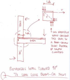
There are other ways to get strength out of the joint. A simple 90° hooked bar or a hairpin will transmit some force around the corner and likely will work sufficiently. However, considering the full flexural capacity of the joint without taking in account the potential deleterious effects of this setup is not appropriate.
So I woke up this morning, popped out of bed, and realized that I
still have a bit more to give on this. And not just petty bickering either. Good stuff.
Everybody seems to want to know how, and how well, the joints work when the stem bars are terminated in a developed hook and no more. Above, I've pitched two explanations for the mechanism/efficiency in such joints: the STM model and the joint clamping mechanism analogous to a perimeter beam column joint.
The major drawback with STM models, of course, is that nobody has time for that stuff in a design office. Additionally, there are some features of the joint behavior that are actually less intuitive when presented in STM than they might otherwise be if presented in terms of traditional sectional design methods.
So... I've decided to generate a proposed
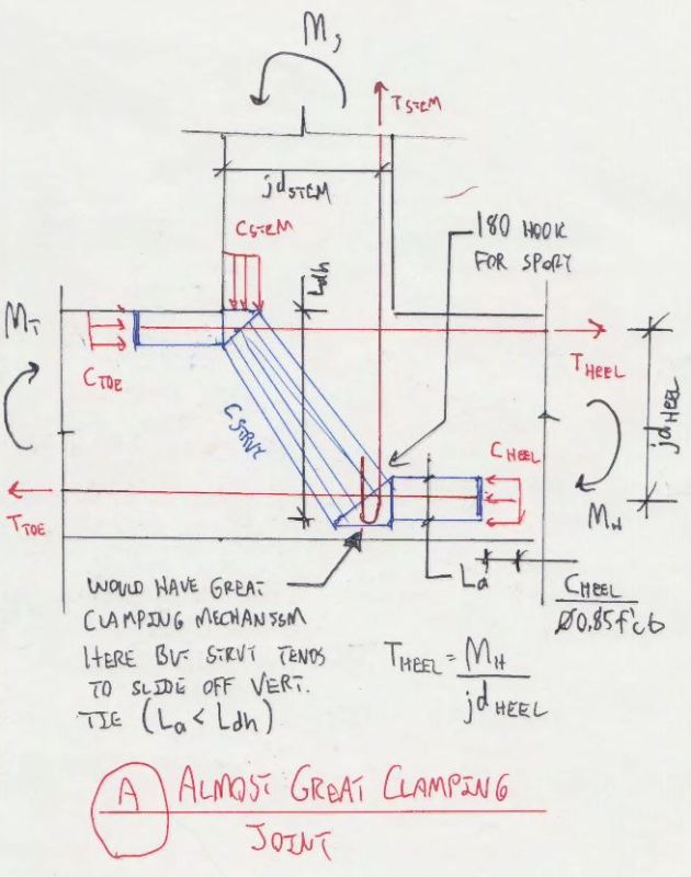
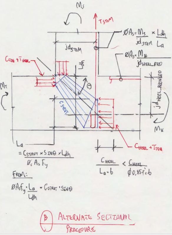
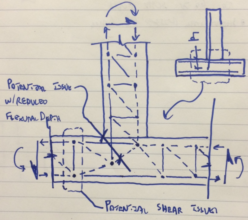
sectional method for the design of these joints as illustrated in the two sketches at the bottom of this post as follows:
1) Detail A shows the excellent clamping mechanism that could be relied on
if only the strut would not slip off of the stem bars due to lack of development. I've assumed that the tension forces in the footing rebar can be conceived of as being pulled across the joint and manifested as additional compression on the other side. We do similar things in strut and tie so I'm comfortable with the validity of the assumption. Really, it's a big part of what makes the clamping mechanism so effective.
2) Detail B shows a proposed method of adjusting the design for the amount of stem bar development actually available. Again, I've assumed that the tension forces in the footing rebar can be conceived of as being pulled across the joint and manifested as additional compression on the other side. Basically, it amounts to this:
2a) Figure out the dimension La to make things pan out. Some iteration might be required.
2b) Increase the heel reinforcing to account for the reduced flexural depth (jd_heel_reduced).
2c) Increase the stem reinforcing to account for the partial rebar development (La vs Ldh).
2c) Check one way shear on heel based on reduced flexural depth.
2d) Ignore the compression strut as we would with other sectional methods (I guess).
2e) Have faith that the system will "find" this load path rather than initiate an anchorage failure along the way.
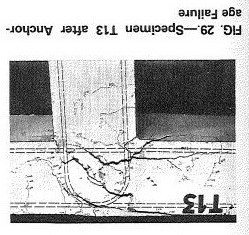
An interesting feature of this is that it provides a couple more ways to explain why we don't see failures with this detailing:
1) We know that current, code specified development lengths are quite conservative. The reduced flexural depth in the heel is probably better than it seems. And the ratio La/Ldh is probably greater than it seems.
2) We know that the probable yield strength of rebar closer 1.25 x fy. This will help to offset the additional rebar required by the inefficiencies inherent in the joint.
I like to debate structural engineering theory -- a lot. If I challenge you on something, know that I'm doing so because I respect your opinion enough to either change it or adopt it.
![[machinegun]](/data/assets/smilies/machinegun.gif "[machinegun] [machinegun]")
![[glasses]](/data/assets/smilies/glasses.gif "[glasses] [glasses]")