Continue to Site

Eng-Tips is the largest engineering community on the Internet

Intelligent Work Forums for Engineering Professionals

  • Congratulations waross on being selected by the Eng-Tips community for having the most helpful posts in the forums last week. Way to Go!

Retaining Wall - Flexural Reinforcement from Stem Into Footing 21

Status
Not open for further replies.

CWEngineer

Civil/Environmental
Jul 3, 2002
269
I am trying to get some clarification regarding the flexural reinforcement of the stem of a retaining wall into the footing.

Does the flexural reinforcement in the stem of a wall, need to be developed into the toe, such as show in Figure 1 of the attached document. Or is providing a standard hook (12db), sufficient, such as that show on Figure 2 of the attached document? If providing a standard hook is sufficient, can the hook be turned towards the heel?

Thanks in advance
 
 http://files.engineering.com/getfile.aspx?folder=8fc7a958-bb23-4694-a010-30dca047d4a9&file=Flexural_Reinforcement.pdf
Replies continue below

Recommended for you

Tomfh said:
Different reinforcement ratios (T12, T16) can see the lapped/continuous bar capacity increase up to 100% capacity (perhaps the hairpin case would increase too, or maybe it maxxes out around 80%)

This was my thought; if demonstrated otherwise I would happily concede that point.

Tomfh said:
What I disagree with is that this proves the STM/pulley model, that it proves a bar with less than full lap is "abominable"

Agreed on both.

Tomfh said:
and that it proves simply wrapping a continuous bar "guarantees" idealized performance. It is a silly to say 79% reflects a dangerous joint and that 82% is perfectly good reliable joint that we needn't look twice at. If one is questionable, the other is too.

Agreed to some degree. While the highest value of the tested "hairpin models" and the lowest values of the tested "KootK Hook™" do almost coincide; the impression I got was improved performance was achieved with the KootK Hook™. But, yes, establishing why there was overlap in the tested values is clearly important and doesn't mean that it's an infallible joint detail. What I meant by "guarantees" idealized performance was that it matches a model that makes sense to me (not saying others are wrong, just that I understand KootK's pulley model best), and it provides rebar continuous around the joint avoiding plain concrete areas that can be broken out in a frustrum "appendix D" style failure mode, something I feel to be quite beneficial. I clearly worded that poorly as I was not trying to imply that it was a perfect joint detail that by bending the bar towards the toe and developing it you automagically achieve 100%+ efficiency.

Tomfh said:
How can 79% be dangerous and 82% safe?

Agreed, it can't. However, I feel that if I took nothing else from this thread; knowing that the KootK Hook™ detail provided 3% or more improved performance in a joint with no downsides then it's at least better than nothing. But, as KootK said, I'd wish to find the truth of what is actually happening in the joint and why both methods have less than 100% efficiency in some tests, what's the maximum possible efficiency out of each style, and what needs to be done to ensure 100%+ all the time.

Tomfh said:
As for the reason for the loss in strength in the hairpin - it is anchorage failure, as noted on nilssons images. The hairpin can pull out easier than a continuous/90degrees bar beacause there is nothing crossing the pullout interface - see image below. This is in line with KootKs ideas, but is not nearly as bad as he imagines.

Agreed on both points. Failure matches what I feared/expected, but neither was perfect.

Tomfh said:
If you want the guaranteed 100% performance you are demanding, with no questions as to reduced capacity, you need diagonals and bandage bars, etc

Perhaps this is the answer. But, yes, if these joints have been a concern in my designs this has been my approach.

Professional Engineer (ME, NH, MA) Structural Engineer (IL)
American Concrete Industries
 
Hi All,

Interesting thread!

My understanding is these "tests" and all the research has been completed for quite a thin (8") wall joint?

What happens with these details if we are talking about a much larger concrete section, say in the stem of a larger wall or a large industrial concrete tank? These section may increase to as much as 18-20" thickness, in these cases are we still looking at the 60-80% joint efficiency with the same or similar details? Or can we increase the joint efficiency without adding the diagonals just because the hooked or hairpin bars for sure are developed past their intersection point in the case of an opening joint?
 
Sweet, some questions that are easy to answer. Well... for the most part.

Everynameistaken said:
My understanding is these "tests" and all the research has been completed for quite a thin (8") wall joint?

- For the retaining walls, it was 8" walls and 10" footings.

- For the T-joints is was an 8" x 8" post hanging down from a beam member of unspecified depth.

Everynameistaken said:
Or can we increase the joint efficiency without adding the diagonals just because the hooked or hairpin bars for sure are developed past their intersection point in the case of

Are you inquiring about the horizontal joint between the walls and the foundations? Or there vertical corner joint where two walls meet?

I like to debate structural engineering theory -- a lot. If I challenge you on something, know that I'm doing so because I respect your opinion enough to either change it or adopt it.
 
Hi,

I think both, is there really that much different between the two except perhaps where we put our construction joint? If they are the same thickness then very similar.

Both flexural members with an opening type joint applying tension to the inside face bars, yes the base to wall stem also could have some compression I guess?
 
Everynameistaken said:
I think both, is there really that much different between the two except perhaps where we put our construction joint? If they are the same thickness then very similar.

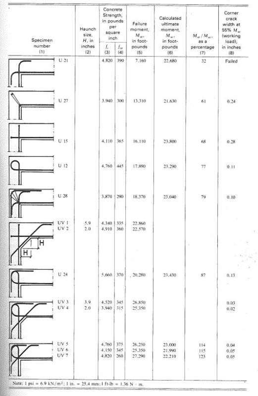
There's a difference. The retaining wall joints benefit from having both a toe and a stem. You get that helpful clamping action that I pitched a few posts back. With the corners, particularly the opening corners, clamping goes out the window and the importance of the rebar detailing becomes exacerbated. The Nilsson data for corner joints is shown below.

The question of scale is an interesting one. As I mentioned previously, where the detail would rely on concrete in tension (breakout), the mathCAD work that I posted above indicated that that would get worse with larger bars. So take that for whatever you think it's worth.

With regard to the size of the concrete members, I'm torn between which of these statements would be most applicable:

1) Member size should scale up in proportion to the rebar tension force (db^2, spacing) in order to keep the efficiency the same. If your members are doubling in size and you're still using small bars at a reasonable spacing, I suspect that your inefficiencies would improve.

2) Member size should scale up in proportion to the rebar diameter (db^1) in order to maintain the same efficiency. As bars get bigger, the bend radii get bigger too and you start pinching your joints if the joint dimensions aren't also scaling up proportionally.

I lean more towards #1 being the dominant effect. That's just my personal opinion though. I've no hard data to back it up.

c01_spfppp.jpg


I like to debate structural engineering theory -- a lot. If I challenge you on something, know that I'm doing so because I respect your opinion enough to either change it or adopt it.
 
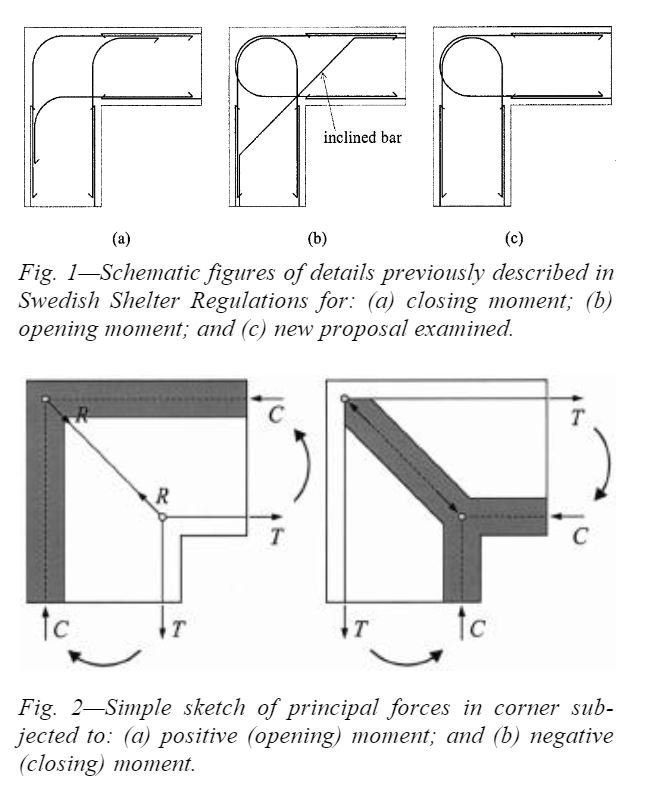
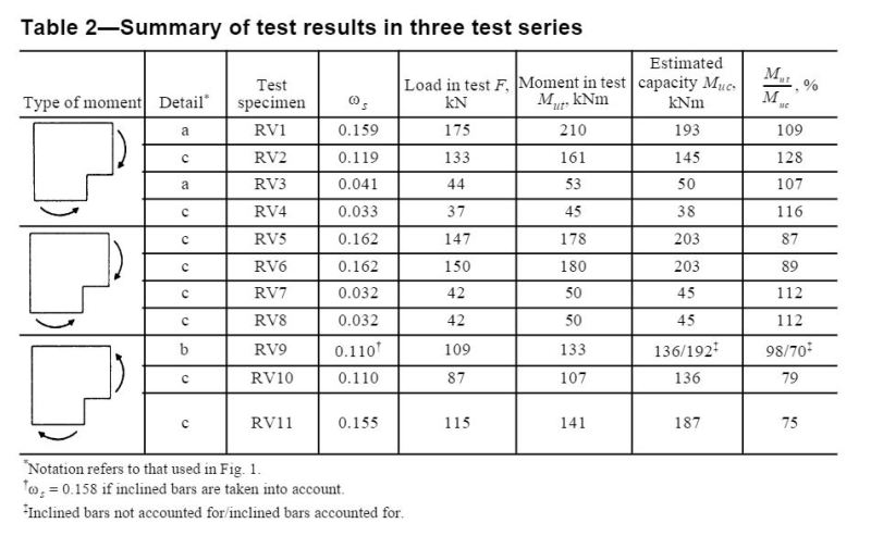
Johansson did some work in 2001 that is interesting as well. Not sure why Nordic folks seem to rock at this. Johansson's studies focused more on closing joints than most other researchers too which is interesting. Basically, as long as you've got a well spliced corner bar set on the outside, the closing joints perform great.

c01_axsmns.jpg


C02_lnhxvk.jpg


I like to debate structural engineering theory -- a lot. If I challenge you on something, know that I'm doing so because I respect your opinion enough to either change it or adopt it.
 
TME said:
Oh, we're going to need a whole entire new thread if you start talking about closing joints KootK.

Ahh... but we've been been talking about closing joints the whole time TME. That's the "pulley". Might as well go for an even 300 here I say!

I like to debate structural engineering theory -- a lot. If I challenge you on something, know that I'm doing so because I respect your opinion enough to either change it or adopt it.
 
It is and it isn't a closing joint.

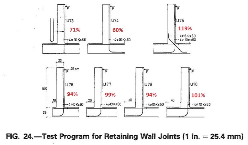
Eg retaining wall U76 is far more opening than closing.
 
I should have said "closing corner joints", and it was meant mostly in jest. Obviously there are important parallels, though as Tomfh said it's a combination of opening/closing (tee joint) so parallels but not directly comparison seem appropriate, agreed?

Professional Engineer (ME, NH, MA) Structural Engineer (IL)
American Concrete Industries
 
TME said:
it's a combination of opening/closing (tee joint) so parallels but not directly comparison seem appropriate, agreed?

I agree that every retaining wall with a stem and a toe is some part opening joint and some part closing joint. That was really my point. Surely you'll give it to me on credit that I did not think that a retaining wall was just a simple closing joint?

TME said:
so parallels but not directly comparison seem appropriate, agreed?

Not agreed. The toe to stem part of the joint absolutely is a closing joint and visualizing it as such is the key to recognizing the appropriate detailing.

I like to debate structural engineering theory -- a lot. If I challenge you on something, know that I'm doing so because I respect your opinion enough to either change it or adopt it.
 
Some of these walls can contain closing joint, but not always.

U73, U74, U76 opening only.

U70, U75, U77, U78 opening and closing

Capture_01_btrinm_1_cioyn4.jpg
 
KootK said:
Surely you'll give it to me on credit that I did not think that a retaining wall was just a simple closing joint?

Of course.

KootK said:
Not agreed. The toe to stem part of the joint absolutely is a closing joint and visualizing it as such is the key to recognizing the appropriate detailing.

While I think I see what you're saying; this quote above appears contrary to your other quote at the beginning of this post. Can you clarify?

Professional Engineer (ME, NH, MA) Structural Engineer (IL)
American Concrete Industries
 
TME said:
Can you clarify?

I'll certainly try. I see every conventional retaining wall joint as a superposition of two joints: a toe-stem closing joint and a heel-stem opening joint. And we know coming in just how much moment transfer capacity is required of each.

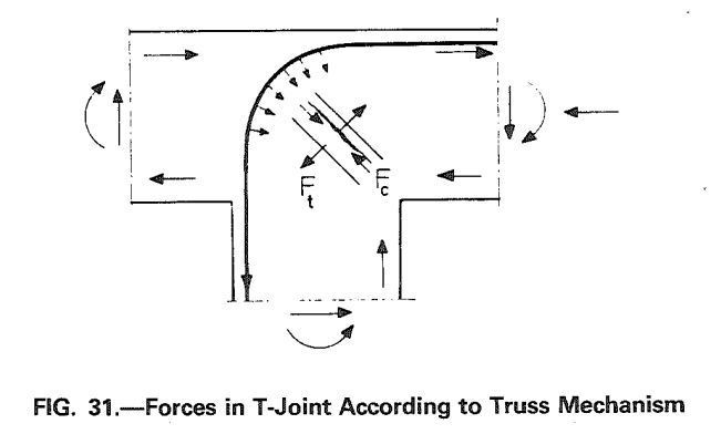
Whatever moment resides in the toe has to be transferred around the closing joint and into the stem. If one wishes to stick with RC concrete principles rather than relying on concrete in tension, as I do, then the flexural tension in the toe rebar needs to round the corner into the stem via a capable corner bar and what we've been calling the pulley STM (my stuff and Johansson's above).

So at the end of the day, the portion of the retaining wall joint that functions as a closing joint is governed by the same mechanics and rational detailing as any other (non-T) closing joint. Thus I see the two as pretty much perfect analogs.

I like to debate structural engineering theory -- a lot. If I challenge you on something, know that I'm doing so because I respect your opinion enough to either change it or adopt it.
 
If we want to arrive at the truth of how concrete works, it's worth acknowledging that all reinforced concrete - the pulley STM model included - relies fundamentally on concrete in tension.

Bar anchorage, shear, "phantom ties", the very fact that concrete is solid - all of this relies fundamentally on tensile forces. When we reinforce concrete we aren't eliminating tension, we are spreading and redistributing the tension out within the concrete so that it is manageable and hopefully the steel is the critical element. But we're still relying on it.

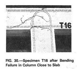
Take the pulley STM model - look at how it fails - tensile overload in the diagonal direction.

Capture_03_d0yijn_bbwydy.jpg


Capture_01_v3v2fd_mbke6n.jpg


These cases start failing at 82% due to concrete tensile overload - failure of the so called "phantom ties". (some give 100% too of course, because the concrete tensile stresses haven't been exhausted).

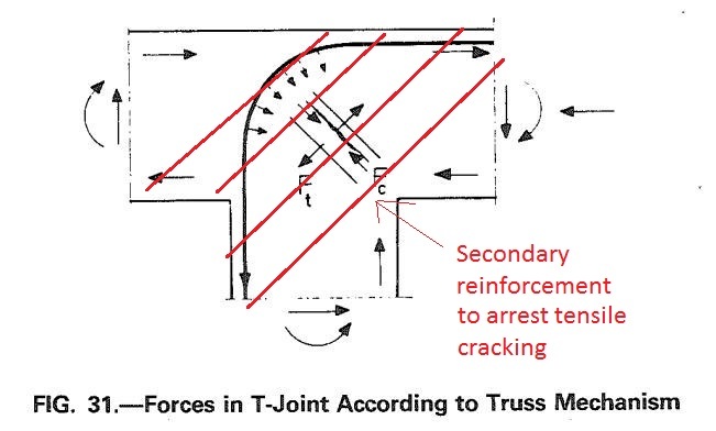
To get the full 100% guaranteed performance you need additional transverse ties to clamp those cracks.

Capture_03_d0yijnties_bnd9ra.jpg


However those transverse tie too rely on their own anchorage - more tensile stress in the concrete!, and so on. By that stage you've gotten to the point you can start ignoring it and pretend you aren't relying on concrete tensile forces.

But if we want arrive at the truth of how it all this stuff work, we need to let go of the comforting belief that we aren't relying on tension in the concrete. In reality, tension keeps it standing.
 
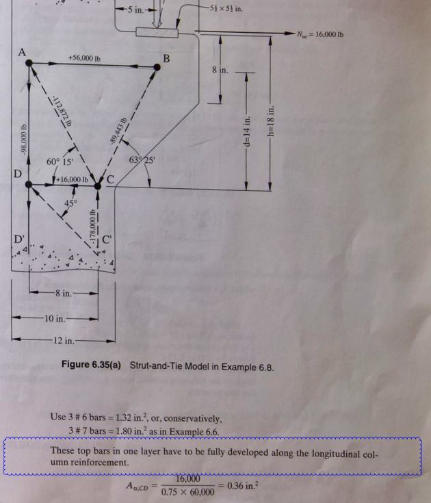
This might be somewhat relevant - I was reading through Nawy's reinforced concrete book on Corbel deign via STM approach and he states that "the top bars in one layer have to be fully developed along the longitudinal column reinforcement. This would seem to go along with the pulley concept, no?

Still struggling with the best way to upload/markup create and share image... so see attached.


EIT
www.HowToEngineer.com
 
 http://files.engineering.com/getfile.aspx?folder=ee30c7e5-3faf-46fd-90cb-fefd46596977&file=Corbel_STM_1.pdf
RF said:
This would seem to go along with the pulley concept, no?

Bingo. Nice add. And you'll see folks using standard hooks in that application too.

C02_ihtdep.jpg


I like to debate structural engineering theory -- a lot. If I challenge you on something, know that I'm doing so because I respect your opinion enough to either change it or adopt it.
 
1) Seems to me there should be a good sized anchor bar inside the bend of the primary tension steel at Point A to spread out the 113,000# compression of strut AC.
2) The #3 anchor bar seems much too small to develop the primary tension steel at the outside of the corbel.
3) There is no mention of anchorage of the 2-#6 framing bars at point D. Do they just stop at the column steel?
4) Compression strut DC' ends up with no tie to resist the horizontal force at C'. Perhaps you need tie D'C' for that purpose.

BA
 
@RFreund: you'd asked about exterior beam column joints before. I stumbled upon this and though it might interest you: Link

I like to debate structural engineering theory -- a lot. If I challenge you on something, know that I'm doing so because I respect your opinion enough to either change it or adopt it.
 
Great report.

Seems be saying that bar stress at the start of the tail remains very low until the joint starts spalling and falling apart, at which case the tail start working hard and presumably keeps it all hanging together a bit longer. Hence nilssons getting 80-100%+ from pulley reinforcement rather than 79% with 180 degree hook (discontinuous pulley).

 
Status
Not open for further replies.

Part and Inventory Search

Sponsor