Continue to Site

Eng-Tips is the largest engineering community on the Internet

Intelligent Work Forums for Engineering Professionals

  • Congratulations waross on being selected by the Eng-Tips community for having the most helpful posts in the forums last week. Way to Go!

Retaining Wall - Flexural Reinforcement from Stem Into Footing 21

Status
Not open for further replies.

CWEngineer

Civil/Environmental
Jul 3, 2002
269
I am trying to get some clarification regarding the flexural reinforcement of the stem of a retaining wall into the footing.

Does the flexural reinforcement in the stem of a wall, need to be developed into the toe, such as show in Figure 1 of the attached document. Or is providing a standard hook (12db), sufficient, such as that show on Figure 2 of the attached document? If providing a standard hook is sufficient, can the hook be turned towards the heel?

Thanks in advance
 
 http://files.engineering.com/getfile.aspx?folder=8fc7a958-bb23-4694-a010-30dca047d4a9&file=Flexural_Reinforcement.pdf
Replies continue below

Recommended for you

Tomfh said:
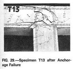
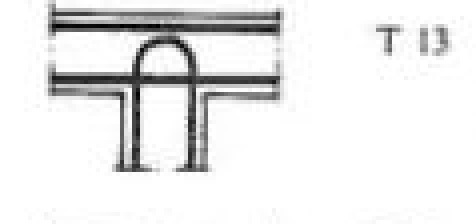
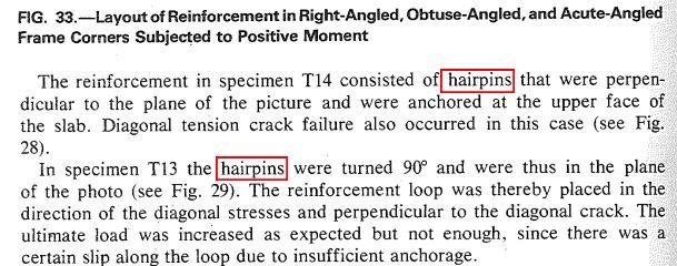
However the T13 hairpin doesn't perform that much worse, and it has no lap whatsoever between the horizontal bar and the hairpin!

I think that the explanation for some of the unexpectedly good performance one gets from poorer joint details originates from the clamping action that one gets when one has both a toe and a heel in play. Under that arrangement, you're getting an averaging effect between the capacities of a weaker joint on the toe side and a stronger joint on the heel side (analogous beam column joint below). I suspect that testing on heel-less retaining wall joints would lead to a greater disparity in the results.

Tomfh said:
So I disagree you need to provide AsFy worth of lap between the horizontal and vertical bars.

I did not say AsFy worth of lap. I said however much lap is required for the M_toe/jd_toe at the splice location.

Tomfh said:
Our case with a standard hook lapping with the horizontal bars presumably does better than the hairpin with virtually no lap.

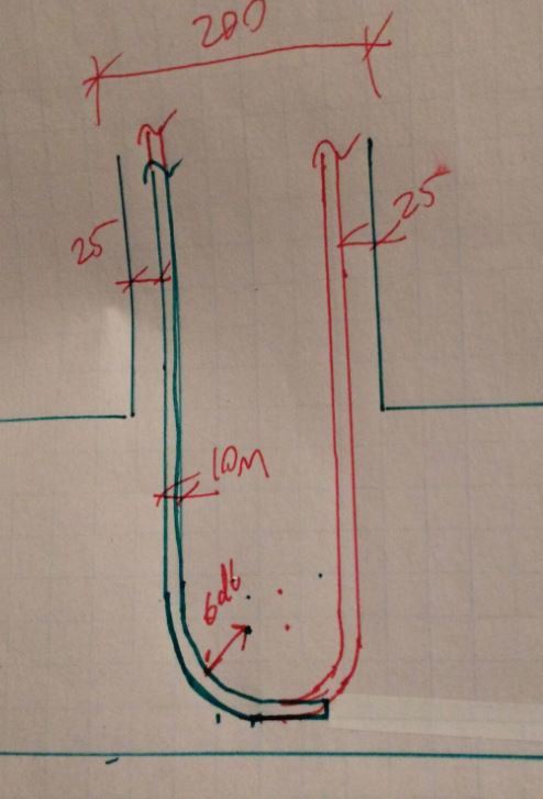
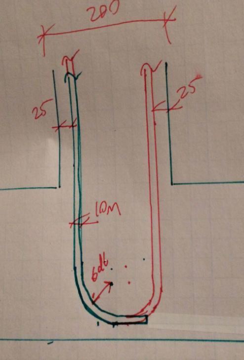
I think that you're underestimating the extent to which the hairpins are just improved standard hooks. I've drawn a 10M standard hook to scale over top of a 10M hairpin below. It's almost the same lap splice dimension with the hairpin having the benefit of the extra upturn on the right to help restrain the strut coming into the corner.

Capture01_eavh51.jpg


Capture_01_ezv40f.jpg


I like to debate structural engineering theory -- a lot. If I challenge you on something, know that I'm doing so because I respect your opinion enough to either change it or adopt it.
 
If you're going to say hairpins beat hooks/cogs I can't but help conclude you're arguing for the sake of it, as you just said you aren't concerned about the vertical bars anchorage (as I thought you were), but are in fact concerned about the horizontal bar's ability to lap onto the vertical bar so it can resolve into the joint.

You said your precise concern was to give the bottom bars something to grab onto.

How does a hairpin, which provides a much shorter lap with the horizontal bar than does a standard 90 degree hook, provide more to grab onto?

Also, is that cog you've drawn truly "to scale"? I don't think it is. This here is more like what a hairpin vs a standard cog looks like:


7531_224_44-tie-bar-reinforced-concrete_btkwdw.jpg


ANotehr version of same thing:

Capture_01_v3v2fd_dlmwgl.jpg
 
Tomfh said:
If you're going to say hairpins beat hooks/cogs I can't but help conclude you're arguing for the sake of it

In my last post, I submitted a sketch showing why I thought that the hairpin would be as good or better than the hook. I don't think that it's fair to be accusing me of being intentionally obstinate when I continue to justify my opinions with new information.

Tomfh said:
How does a hairpin, which provides a much shorter lap with the horizontal bar than does a standard 90 degree hook, provide more to grab onto?

As I showed in my to-scale sketch above, the flat part of the hook/hairpin that lap splices is nearly identical for the small bars that would typically be used for a hairpin. So, as I see it, the lap length for the two arrangements is nearly identical and the hairpin has the added benefit of an extra "hook at the end of the hook" as it were. I don't see how that could do anything but help matters with regard to splicing.

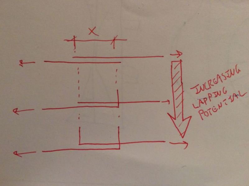
I think of it as I've shown in the sketch below. For the same lap length X, it seems intuitive to me that the versions with one or more hooks would do a better job of splicing.

Tomfh said:
Also, is that cog you've drawn truly "to scale"? I don't think it is.

It is indeed to scale including: member size, bar size, bar radius. Obviously, I didn't spend hours and hours making it perfect. Probably about five minutes.

Tomfh said:
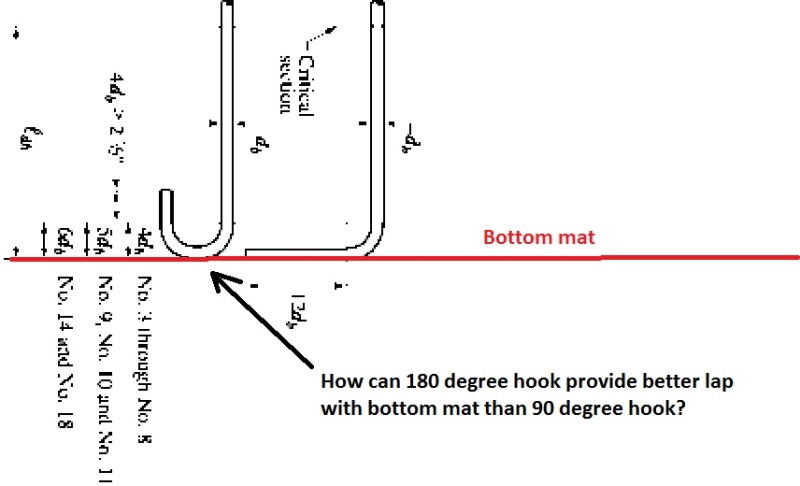
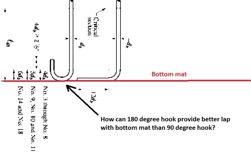
This here is more like what a hairpin vs a standard cog looks like... How can a 180 degree hook provide a better lap with bottom mat that 90 degree hook?

A hairpin and a 180 hook are not the same thing and do not have the same geometry. In general, a hairpin will have a longer flat spot at the bottom.

Capture_01_f5k1jx.jpg


I like to debate structural engineering theory -- a lot. If I challenge you on something, know that I'm doing so because I respect your opinion enough to either change it or adopt it.
 
Tomfh said:
This doesn't work at all according to pulley analogy yet in reality, is almost as efficient as unbroken bar

It's not as though I've been saying that the joint has no capacity if it's not detailed and designed according to the STM/pulley analogy. What I've been saying is:

1) Capacity will be maximized and best reflect designer determined capacity when detailing is done according to the STM/pulley scheme.

2) Other schemes will have some capacity but that capacity would be a) less than the STM/pulley detailing capacity and b) difficult for designers to estimate reliably.

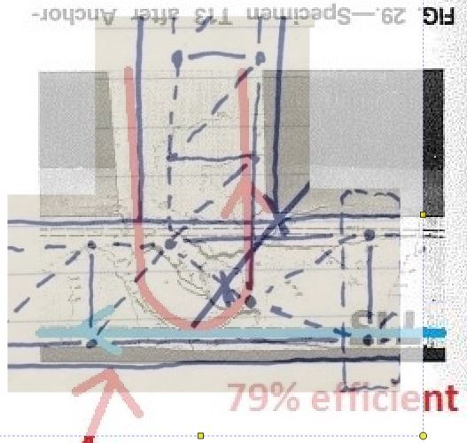
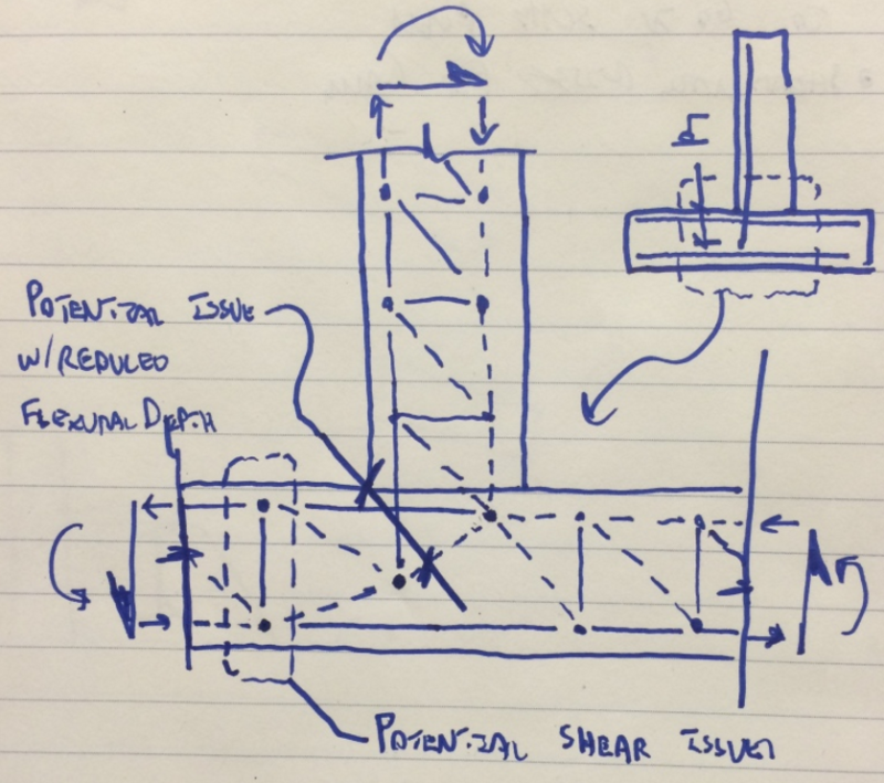
I previously posted an STM model for the case where the stem bars are developed but do not turn the corner. I believe that model would be relevant to the u-bar case here. Below, I`ve superimposed that STM over the photo of the cracked u-bar specimen. As you can see, they correlate nicely with regard to strut and crack formation.

Capture_01_krswsf.jpg


Original_STM_h0cc9z.jpg


I like to debate structural engineering theory -- a lot. If I challenge you on something, know that I'm doing so because I respect your opinion enough to either change it or adopt it.
 
KootK said:
As I showed in my to-scale sketch above

I've never seen a 90 degree bend that looks like that, and it doesn't look like any of the standard cogs in the various concrete codes. 90 degree bends have a straight extension.

KootK said:
So, as I see it, the lap length for the two arrangements is nearly identical and the hairpin has the added benefit of an extra "hook at the end of the hook" as it were.

These are to scale (again, yours isn't). You are claiming a hairpin 180 degree bend provides better splice to the horizontal bar than a 90 degree bend. I'm very surprised you would argue such a thing.

7531_224_44-tie-bar-reinforced-concrete_btkwdw_soxkll.jpg


KootK said:
In general, a hairpin will have a longer flat spot at the bottom.

Really?? Semi-circles contain longer straight lines than do straight lines?!? That's crazy talk.
 
KootK said:
1) Capacity will be maximized and best reflect designer determined capacity when detailing is done according to the STM/pulley scheme.

Yes, capacity is maximised with a belts and braces approach.

KootK said:
2) Other schemes will have some capacity but that capacity would be a) less than the STM/pulley detailing capacity and b) difficult for designers to estimate reliably.

Such joints show about 80% capacity. To get the full 100% reliably you need to start using diagonals etc.

KootK said:
As you can see, they correlate nicely with regard to strut and crack formation.

Of course. The strut and tie is a simplistic model of the concrete and steel forces, so of course they correlate. But there are areas where they don't correlate, e.g. the fact that a hairpin provides 80% capacity when it should provide next to no capacity according to STM/pulley model. You think about that mismatch between your model and the results.
 
Tomfh said:
I've never seen a 90 degree bend that looks like that, and it doesn't look like any of the standard cogs in the various concrete codes. 90 degree bends have a straight extension.

Tomfh said:
Really?? Semi-circles contain longer straight lines than do straight lines?!? That's crazy talk....You are claiming a hairpin 180 degree bend provides better splice to the horizontal bar than a 90 degree bend.

Nope. I didn't say a thing about 180 bends. I'm claiming that a hairpin would be better than a 90 bend. Everywhere that I've practiced, hairpins and 180 hooks are physically different things. Namely:

1) 180 hooks have no flat spot at the apex.

2) Hairpins will have whatever flat spot is required to fill up the space between the faces of the member, less cover.

The sketches below show the difference conceptually, by somebody else's code. The 4 x dia dimension on the right would be extended to suit the member width.

Capture_01_ibfef5.jpg


I like to debate structural engineering theory -- a lot. If I challenge you on something, know that I'm doing so because I respect your opinion enough to either change it or adopt it.
 
Nilson's results show 180 degree bends. I've been talking 180 degrees bends. You drew 180 degree bends (in your "to scale" sketch).

Now you're trying to sneak in trombones.


Anyway KootK, like the others, I'm done here.

You're now arguing a vertical bar with 180 degree bend provides superior "longer" lap into the bottom steel than a 90 degree hook. So we're done.

Clearly you have little interest in having an honest look at this question and getting to the bottom of it if you are making such ridiculous assertions.
 
Tomfh said:
the fact that a hairpin provides 80% capacity when it should provide next to no capacity according to STM/pulley model.

Tomfh said:
But there are areas where they don't correlate, e.g. the fact that a hairpin provides 80% capacity when it should provide next to no capacity according to STM/pulley model.


Who said that a hairpin would provide next to nothing? Not me. As I said just a few moments ago, there are lesser schemes, and they have lesser capacity. Compared to 100%, I consider 79% to be a lesser capacity.


I like to debate structural engineering theory -- a lot. If I challenge you on something, know that I'm doing so because I respect your opinion enough to either change it or adopt it.
 
A vertical bar with a 180 bend does not satisfy the pulley model in the slightest.

As I said, you're now arguing the vertical bar with 180 degree bend provides superior "longer" lap into the bottom steel than does a 90 degree hook. So we're done. Not going to debate with someone who maintains absurdities like that so as to defend their position.
 
Tomfh said:
You're now arguing a vertical bar with 180 degree bend provides superior "longer" lap into the bottom steel than a 90 degree hook. So we're done.

Again, hairpins not 180 bends. They are different products in my realm.

Tomfh said:
I'm done here...Clearly you have little interest in having an honest look at this question and getting to the bottom of it.

I would argue that I've done more to get to the bottom of this particular question than pretty much anyone else on this board. I don't appreciate having my contributions diminished just because you have debate fatigue.


I like to debate structural engineering theory -- a lot. If I challenge you on something, know that I'm doing so because I respect your opinion enough to either change it or adopt it.
 
Tomfh said:
A vertical bar with a 180 bend does not satisfy the pulley model in the slightest.

I never said that it did. In fact, I went to great trouble to develop another, non-pulley STM model to suit the case where the stem bar is only developed. It's not like there's just one STM model available for use. We generate one (or more) STM to suit each particular detailing scheme.

To clarify, the STM below is the one that I have proposed for stem bars that end in 90 hooks or 180 hooks, not the pulley STM.

C01_tk6frv.png


I like to debate structural engineering theory -- a lot. If I challenge you on something, know that I'm doing so because I respect your opinion enough to either change it or adopt it.
 
KootK said:
Again, hairpins not 180 bends.

You drew a 180 bends. You referred to Nillson who showed 180 bends. I referred to 180 bends. You said these provided superior lap to bottom bars than does a 90 bend.
 
Tomfh said:
Nilson's results show 180 degree bends.

I don't understand how you could know that. They look like hairpins to me.

Tomfh said:
I've been talking 180 degrees bends.

I know it. I've been trying to get you to stop talking about them all day.

Tomfh said:
You drew 180 degree bends (in your "to scale" sketch).

I'll be the judge of the intent of my own sketches and I've drawn hairpins.

Tomfh said:
Now you're trying to sneak in trombones.

I'm not trying to sneak anything in Tom. I tied to show you what I mean: the difference between a hairpin and a 180 hook.


I like to debate structural engineering theory -- a lot. If I challenge you on something, know that I'm doing so because I respect your opinion enough to either change it or adopt it.
 
Tomfh said:

Even though I'm not sure Tomfh will read this; I reread through most of this topic and while KootK has said some slightly antagonistic comments or defended his position in a fairly aggressive way I feel that overall KootK has attempted to maintain a balanced approach to the debate while Tomfh has been increasingly argumentative and insistent that KootK is altering his argument and/or deliberately avoiding conceding points of debate. Further, near the end, while KootK did become fairly defensive (and I see nothing wrong with this) Tomfh has resorted to increasingly accusative and pejorative language, finally culminating in petty name calling.

I'll summarize this later if you disagree with my assessment. Overall I feel KootK has been wronged by your posts here Tomfh and you owe him an apology and should probably not post in this topic again if you can't debate as a professional.

Professional Engineer (ME, NH, MA) Structural Engineer (IL)
American Concrete Industries
 
KootK repeatedly denied drawing a 180 degree hook, claming he drew a trombone hairpins. Here is what he drew:

Capture_01_ezv40f_r07gyn.jpg


KootK denied Nillson drew 180 bends, but drew tromboine hairpins. Here are Nilsson's drawings.

Capture_01_v3v2fd_2_xscm0k.jpg

Capture01_ligl0z_edfx0f.jpg


I corrected KootK, and he again denied Nilsson drew 180 hooks, and again denied drawing 180 hooks, claiming Nilsson's hooks "look like [trombone] hairpins to me", and "I'll be the judge of what I drew, I drew [trombone] hairpins"


TME said:
Overall I feel KootK has been wronged by your posts here Tomfh and you owe him an apology and should probably not post in this topic again if you can't debate as a professional.

He maintained a falsehood. I gave him several chance to change tack, but he held his line, so I called him on it. If it is unprofessional of me to point it out then so be it.
 
Tomfh said:
KootK repeatedly denied drawing a 180 degree hook, claming he drew a trombone hairpins. Here is what he drew:

And in that same post, I introduced the sketch like this:

KootK said:
I think that you're underestimating the extent to which the hairpins are just improved standard hooks. I've drawn a 10M standard hook to scale over top of a 10M hairpin below.

Tomfh said:
KootK denied Nillson drew 180 bends, but drew tromboine hairpins. Here are Nilsson's drawings.

- The pictures do not state whether the bends are hairpins or 180 hook.

- You have interpreted the pictures as 180 hooks.

- I have interpreted the pictures as hairpins because they are 10M and appear to extend to the cover distance.

My interpreting a diagram differently from you doesn't make me a liar Tom. "Hairpin" may just be a term that is used differently in our respective markets. For what it's worth, the blurb below is from the Nilsson document. Obviously, you don't have the whole thing so there was no way for you to know definitively one way or another. I didn't know definitively until just now either. I just checked it out now to make sure that I wan't an accidental liar. At the very least, I think that this demonstrates that my interpretation of the diagrams was at least as valid as yours.

Capture_01_kz3eqh.jpg


I like to debate structural engineering theory -- a lot. If I challenge you on something, know that I'm doing so because I respect your opinion enough to either change it or adopt it.
 
KootK, I apologize for calling you a liar, I should have just stuck to the facts.


I'm sure you can appreciate how frustrating it is to hear you insist that the horizontal bars needs a full lap onto the vertical bars, and then completely dismiss the fact that a 180 hook example gets close to full capacity without any such lap, and then go off on some tangent about trombones...
 
TME said:
I reread through most of this topic and while KootK has said some slightly antagonistic comments or defended his position in a fairly aggressive way I feel that overall KootK has attempted to maintain a balanced approach to the debate...Further, near the end, while KootK did become fairly defensive (and I see nothing wrong with this)

Thanks for defending my honor TME. Seriously, you have my genuine, non-sarcastic thanks. It gets a little cold and lonely out in agitator-land at times.

This thread has a fairly wide audience, both in terms of active participants and lurkers (I hear from them through other channels). It's also the thread where my particular style of debate has been highlighted the most. Consequently, I'd like to take the opportunity to explain my style of debate. This will be one post of, what, 250 here? I'll accept the hijacker tag.

Engineers are generally good, humble folk who do their best to avoid unnecessary confrontation. And it shows here. In my estimation, most forum members just want to dole out their practical solution to whatever practical question has been asked and move on. If differing advice crops up, they're usually happy to agree to disagree.

I'm a little different. I'm constantly, and vigorously in search of the structural "truth" to the extent that there is such a thing. Whenever I see two brilliant engineers offer differing advice without taking it to the mat in a spirited debate, I see a wasted opportunity to chase down the the truth. And lets not kid ourselves, for many things, there really is a best answer. We just have to flesh it out.

Hokie66 once referred to one of my previous sparring partners as somewhat abrasive. I like that. That's how I would like to be regarded. Sometimes I'm abrasive so that I can drive my points home. Other times, I'm abrasive in attempt to cajole my sparing partners into driving their points home. Always, the goal is to try and tease out a better understanding and, where possible, a legitimate consensus.

I get that some folks find my style of debate obnoxious. And I feel badly about that when things start to boil over, truly. On the other hand, I feel that the tenacity with which I prosecute technical debates here leads to a lot of interesting and valuable technical growth. It is, and has always been, my hope that the benefits of the latter outweigh the frustrations associated with the former. Think of me like Michael Vick. You might not want to hang with me on the weekend but you gotta admit, I do keep things marching downfield.

I like to debate structural engineering theory -- a lot. If I challenge you on something, know that I'm doing so because I respect your opinion enough to either change it or adopt it.
 
Status
Not open for further replies.

Part and Inventory Search

Sponsor