Continue to Site

Eng-Tips is the largest engineering community on the Internet

Intelligent Work Forums for Engineering Professionals

  • Congratulations waross on being selected by the Eng-Tips community for having the most helpful posts in the forums last week. Way to Go!

Retaining Wall - Flexural Reinforcement from Stem Into Footing 21

Status
Not open for further replies.

CWEngineer

Civil/Environmental
Jul 3, 2002
269
I am trying to get some clarification regarding the flexural reinforcement of the stem of a retaining wall into the footing.

Does the flexural reinforcement in the stem of a wall, need to be developed into the toe, such as show in Figure 1 of the attached document. Or is providing a standard hook (12db), sufficient, such as that show on Figure 2 of the attached document? If providing a standard hook is sufficient, can the hook be turned towards the heel?

Thanks in advance
 
 http://files.engineering.com/getfile.aspx?folder=8fc7a958-bb23-4694-a010-30dca047d4a9&file=Flexural_Reinforcement.pdf
Replies continue below

Recommended for you

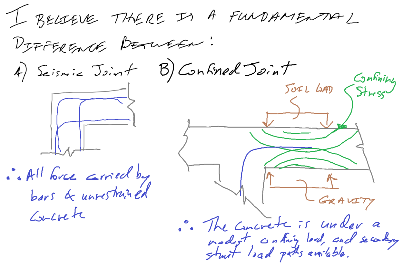
Seismic_Joint_vr_confined_JointUntitled_arkkxk.png


But I still will detail the joints as per our discussion here, and don't like the idea that the hook is simply terminated. All types of anchors, as well as development of regular bars, must occur in zones which are not under tension, plastic hinging or similar.

It's just the physics I think we need to understand better...
 
A few things that I'd like to clarify here:

1) The testing that I've been reviewing has been overwhelmingly monotonic. The reported deficiencies, as far as I know, have nothing to do with blast, fatigue, seismic, or any other manner of cyclic loading.

2) With regard to what has worked for generations, I take that to be the CRSI diagonal bar detail. And, thankfully, that detail tests well. Unfortunately, it has become clear from this thread and my personal practice that many engineers are now omitting the diagonal bars. Based on the testing, that would seem to be a matter of some concern as what we're currently doing tests poorly and is, in fact, not what has worked well for us for generations.

3) Whenever folks don't like the results of my STM arguments, they're often quick to toss me into the "Basket of Deplorable STM Lovers". "Overthinking" as it were.

Firstly, I have not suggested that everyone run off and start designing these joints via STM. Above, I've explicitly indicated that even I don't do that. I've simply been doing what I usually do: using STM as a rational basis for discussing the mechanics of the situation.

Secondly, to my knowledge, STM is pretty much the only established tool that we have available to us for analyzing joints (disturbed regions) that have not been extensively tested. When I make use of STM to examing problems and get accused of "over thinking", what I hear in my head is "I don't like the answer so I'm just going to refuse to acknowledge the problem". STM doesn't need to be the method of design but, if an engineer can't find some way to justify a connection schematically via STM, I will always question whether or not that engineer has really identified a valid load path.

I like to debate structural engineering theory -- a lot. If I challenge you on something, know that I'm doing so because I respect your opinion enough to either change it or adopt it.
 
There are thousands of retaining walls built of CMU, not one of which has anything approaching the diagonal bad shown in thr CRSI detail.

They too have been successfully used for generations without an abnormal number of failures.

I am a big fan of STM, and have used it in professional work. I just think you are overlooking confinement forces that assist. And a fully developed bar extending beyond into the footing is not the sinful and crap detail you've derided above despite my FBD being "one of the classic offenders with respect to retaining wall joint detailing."

Did you misunderstand what I showed? It was not simply a 90 deg hook developed into the footing, but a FBD of the standard detail used all over the world, not the junk detail where the bar never leaves the area under the stem.
 
CELinO said:
There are thousands of retaining walls built of CMU, not one of which has anything approaching the diagonal bad shown in thr CRSI detail.

True. But then I would attribute the lack of failures to the same two factors that I listed previously for concrete walls: load and material factors and the low probability of the estimated soil pressures coming to pass. I would add to that the fact that we design CMU to relatively low stresses and, as such, we do not work block walls nearly so hard as we do concrete walls.

CELinO said:
I just think you are overlooking confinement forces that assist.

Okay, so how does one go about using those confinement forces to quantitatively demonstrate that a joint is adequate when the only criterion met is bar development? As structural engineers, we're usually in the business of what can be demonstrated, not what can be qualitatively imagined.

CELinO said:
Did you misunderstand what I showed? It was not simply a 90 deg hook developed into the footing, but a FBD of the standard detail used all over the world, not the junk detail where the bar never leaves the area under the stem.

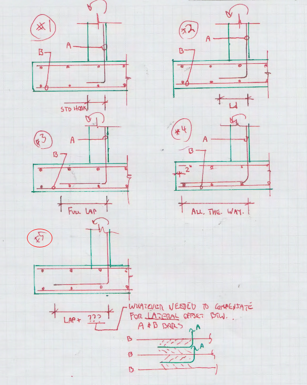
Not sure. I'm familiar with five versions of your detail, as shown and listed below.

#1. Standard hook. Abomination. I see this in about 45% of cases where a detail like yours is used.

#2. Ld. Better but still a fail. The A & B bars need to be lapped, not just developed. I see this in about 10% of cases where a detail like your is used.

#3. Full tension lap. Close but not quite good enough. The lap needs to account for the lateral offset between the A & B bars (via non-contact lap or STM). I see this in about 5% of cases where a detail like yours is used.

#4. Maximum extension to end of toe. Adequate but probably by accident rather than understanding. At this point, there's really no need to have the separate bottom mat of reinforcement unless there is some oddball reason for it in the heel. We're just wasting material and telegraphing our ignorance. I see this in about 40% of cases where a detail like yours is used.

#5. All good. I've yet so see this once in practice.

Perhaps your are that one dude in all of the milky way who's doing a legitimate #5. You tell me.

Capture01_eo3ebg.png


I like to debate structural engineering theory -- a lot. If I challenge you on something, know that I'm doing so because I respect your opinion enough to either change it or adopt it.
 
Why is a hook an abomination if the bar embedment plus hook is sufficient to develop the bar?

Is there any evidence of standard hooks embedded 10 inches deep tearing out of retaining wall footings?
 
Tomfh said:
Why is a hook an abomination if the bar embedment plus hook is sufficient to develop the bar?

At this point, I'll have to assume that you're either joking or trying to get me to embark upon a program of cutting / self-immolation.

I like to debate structural engineering theory -- a lot. If I challenge you on something, know that I'm doing so because I respect your opinion enough to either change it or adopt it.
 
KootK said:
At this point, I'll have to assume that you're either joking

Im not joking. It's a genuine question.

If bars break before concrete breaks then what's the problem with that arrangement?
 
KootK said:
The lap needs to account for the lateral offset between the A & B bars (via non-contact lap or STM)

Forgive me but shouldn't there be no effective difference in the lap-splice length for contact or non-contact lap splices? Why do we need to account for it here? Apparently my retaining wall joints fall in your 5%... So close.

Professional and Structural Engineer (ME, NH, MA)
American Concrete Industries
 
Now, now... No pulling a Budhist Monk on us Kootk; You're well valued and liked around here... If people are asking questions it is to learn. I hope. And put away the razor blades; None of us are fourteen and in love for the first time anymore (lost a good friend to three years of psychiatric treatment to that one, so it takes a fair amount of strength to try to make a joke).

"Forgive me but shouldn't there be no effective difference in the lap-splice length for contact or non-contact lap splices?"

There is a major difference between non-contact and contact lap splices. The distance of separation must be added to the length of the lap splice. This is well treated in many codes, though I do not know the ACI code well enough to swear to it being addressed, it *is* well addressed by the ACI committee on lap splicing. See
Back to the point at hand: The "all the way" detail is standard practice in New Zealand, and what I typically detail unless it is a particularly long toe in the footing. It is is particularly long, then I do No. 5. I'm not kidding, and can probably dig up three or four examples from my records if you want to see it done in practice.

Quick question: Do you really not like the steel extended to the heel? I actually like to include this as temperature and shrinkage, and just to keep the thing easy to construct. I would worry that if you curtail these bars, and the Contractor mixed things up, they might curtail the TOE bars! Take that plus an over-zealous pour, or a pre-pour rebar check by a green intern who misses the issue and blamo you've got a real problem...
 
WAIT... Just checked my records and I don't do five. I would have to call mine an option "6", where the full development length, including compensation for offset lap splice, starts from the toe-side of the stem to footing interface. So my lap is longer than you think it needs to be; You may continue to believe that no one does it your <<All good/Never seen in practice>> option. *friendly rib jab*

And while I have no reason for doing that beyond my hatred of development within a beam-column joint (which is likely a habit from all my seismic and blast work), I will keep doing it and much prefer to start my development lengths outside of anything that looks like a beam-column joint.

I am genuinely enjoying this discussion; I really hope it isn't coming at the expense of anyone's sanity or zen. *looks at KootneyKid semi-concerned*

And I still think our theories must match reality, not the other way around. I just don't buy that all these retaining walls are only surviving because of load factors and other conservatism. Even if that is true, it only means that we should be reducing our load factors in order to produce economical designs. We are in the business of efficient use of client and overall economic resources, not Pyramid building....

On a personal note, I think we may have found something I am sufficiently interested in to go back to Uni and research...
 
"I've looked over it. I still can't see what's so bad about a hook going into the bottom of the footing. KootKs fig 13-28 above calls it satisfactory."

13-28 shows the bar leaving the beam-column (like) joint and being developed into the toe, not just a plain 90 deg hook development. You can't reliably develop a 90 deg hook in a tension or high (unconfined) shear zone. That's why it needs to go through to the toe, where it will be in a mat of concrete under compression/subjected to the compression strut coming from the stem.
 
CELinO said:
13-28 shows the bar leaving the beam-column (like) joint and being developed into the toe, not just a plain 90 deg hook development.

Yes, that's what I was referring to. Sorry for the confusion. The cog leaving into the toe so that the hook grabs onto nicely confined concrete. The other way isn't as efficient...

Personally I do #4 except with the steel going under the bottom mat.

CELinO said:
And I still think our theories must match reality, not the other way around. I just don't buy that all these retaining walls are only surviving because of load factors and other conservatism.

I agree here. We engineers love to second guess reality. Either reality being wrong when something that the calcs say works doesn't end up working, or vice versa and saying something "should have failed".
 
CELinOttawa said:
"Forgive me but shouldn't there be no effective difference in the lap-splice length for contact or non-contact lap splices?"

There is a major difference between non-contact and contact lap splices. The distance of separation must be added to the length of the lap splice. This is well treated in many codes, though I do not know the ACI code well enough to swear to it being addressed, it *is* well addressed by the ACI committee on lap splicing. See

Hmmmm, I don't know much of the international codes so maybe this is a non-US thing? I'm almost 100% sure that ACI 318 does not require any special treatment of non-contact lap splices short of verifying that they're not spaced too far. Further, I didn't fully re-read ACI 408 but the the non-contact lap splice section in there doesn't appear to mention that lapped bar spacing needs to be considered and showed that the bond strength improved for non-contact lap splices.

Am I missing something?

Professional and Structural Engineer (ME, NH, MA)
American Concrete Industries
 
TME said:
Am I missing something?

Nope. I was a bit imprecise with my terminology. I consider there to be two types of non-contact lap splices per North American codes:

1) Non-contact laps between bars less than 6" apart in which case no addition need be made to the lap length.

2) Non-contact laps between bars greater than 6" apart in which lap lengths need to be extended via STM theory, methods found in foreign codes, or judgment.

So yeah, depending on your bar spacings, there are cases where regular tension laps would get the job done.


I like to debate structural engineering theory -- a lot. If I challenge you on something, know that I'm doing so because I respect your opinion enough to either change it or adopt it.
 
CELinO said:
Quick question: Do you really not like the steel extended to the heel?

Obviously, it's not a problem from a performance perspective. It makes me queasy on two fronts:

1) It seems to befuddle designers. Most of the time when I see the bottom mat, I also see the hook bar details that I dislike.

2) It strikes me as wasteful in many applications.

I like to debate structural engineering theory -- a lot. If I challenge you on something, know that I'm doing so because I respect your opinion enough to either change it or adopt it.
 
CELinO said:
And I still think our theories must match reality, not the other way around.

Tomfh said:
I agree here. We engineers love to second guess reality. Either reality being wrong when something that the calcs say works doesn't end up working, or vice versa and saying something "should have failed".

I disagree with these sentiments strongly on a philosophical basis. We are applied scientists and the scientific method works like this:

1) Observe something.
2) Construct a theoretical model to explain what you observe.
3) Test your model in a controlled environment.
4) Confirm or refute your theoretical model.

To devalue the importance of the theoretical model is to throw true understanding out the window altogether.

Past history of performance without a testing validated model has value but is, without question, a weak form of understanding.

I do not accept that a retaining wall designed with safety factors and field tested against wildly unpredictable soil pressures constitutes "a controlled environment".

The testing on opening and closing joints has already been performed and some of it has been posted above. That is step three and it has definitively identified a problem with some of our details. The missing piece of the puzzle here seems to be that you guys refuse to accept the testing as relevant to retaining wall joints.


I like to debate structural engineering theory -- a lot. If I challenge you on something, know that I'm doing so because I respect your opinion enough to either change it or adopt it.
 
CELinO said:
You can't reliably develop a 90 deg hook in a tension or high (unconfined) shear zone. That's why it needs to go through to the toe, where it will be in a mat of concrete under compression/subjected to the compression strut coming from the stem.

I disagree with this. The whole point of a hooked anchorage is to quickly develop the tension potential of a reinforcing bar. It would be useless if it didn't apply in tension zones. Most exterior beam column joints have hooked development taking place withing a region of flexural tension and high shear. The reason that the bars need to go around the corner is because the tension force needs to go around the corner. And that's not the same thing as bar development.

Tomfh said:
Why is a hook an abomination if the bar embedment plus hook is sufficient to develop the bar?
Tomfh said:
Im not joking. It's a genuine question.
Tomfh said:
Yes, that's what I was referring to. Sorry for the confusion. The cog leaving into the toe so that the hook grabs onto nicely confined concrete.

So we're in agreement then? #1 is a detailing abomination?

I like to debate structural engineering theory -- a lot. If I challenge you on something, know that I'm doing so because I respect your opinion enough to either change it or adopt it.
 
KootK said:
So we're in agreement then? #1 is a detailing abomination?

No, I don't agree with that. I agree with your link that it appears a satisfactory detail. Not necessarily the absolute best detail, but satisfactory. It's silly to call it "an abomination" when it can yield the bars and has proven itself the world over.

An "abomination" is detail posted above where the cog is barely embedded at all, and sitting in the very top of the footing.

Personally I do #4, except the cog goes under the bottom cross bars.
 
Status
Not open for further replies.

Part and Inventory Search

Sponsor