Continue to Site

Eng-Tips is the largest engineering community on the Internet

Intelligent Work Forums for Engineering Professionals

  • Congratulations waross on being selected by the Eng-Tips community for having the most helpful posts in the forums last week. Way to Go!

Retaining Wall - Flexural Reinforcement from Stem Into Footing 21

Status
Not open for further replies.

CWEngineer

Civil/Environmental
Jul 3, 2002
269
I am trying to get some clarification regarding the flexural reinforcement of the stem of a retaining wall into the footing.

Does the flexural reinforcement in the stem of a wall, need to be developed into the toe, such as show in Figure 1 of the attached document. Or is providing a standard hook (12db), sufficient, such as that show on Figure 2 of the attached document? If providing a standard hook is sufficient, can the hook be turned towards the heel?

Thanks in advance
 
 http://files.engineering.com/getfile.aspx?folder=8fc7a958-bb23-4694-a010-30dca047d4a9&file=Flexural_Reinforcement.pdf
Replies continue below

Recommended for you

Tomf said:
I agree with your link that it appears a satisfactory detail.

I believe that you are mistaken. There is no link of mine indicating that a standard hook on the stem verts is acceptable. Certainly, that is not what figure 13-28 indicates. Figure 13-28 shows the hooks being extended out to the toe.

Tomfh said:
It's silly to call it "an abomination" when it can yield the bars and has proven itself the world over.

The details that have been proven the world over are the CRSI detail with the diagonal bars and, to a lesser extent, the #4 detail with the bars extended to the toe. What is silly, in my opinion, is confusing simple bar development with proper joint design. If all it took to design a joint were bar development, why has the world bothered with:

1) Developing the strut and tie method? Lot's of effort there.

2) Developing joint design guides like this and this.

Why publish hundreds of pages on joint design when it could just all be summed up with "develop the bars"? That would take what, a paragraph? Silly researchers and code committees...

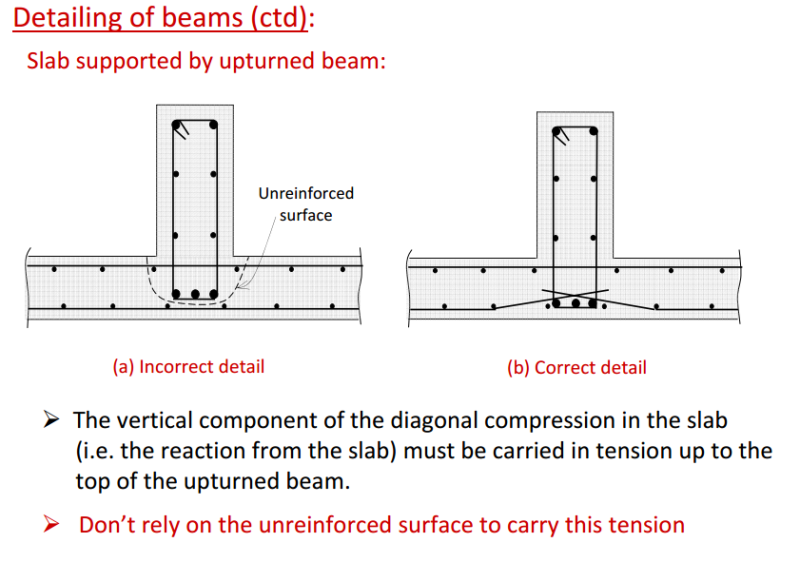
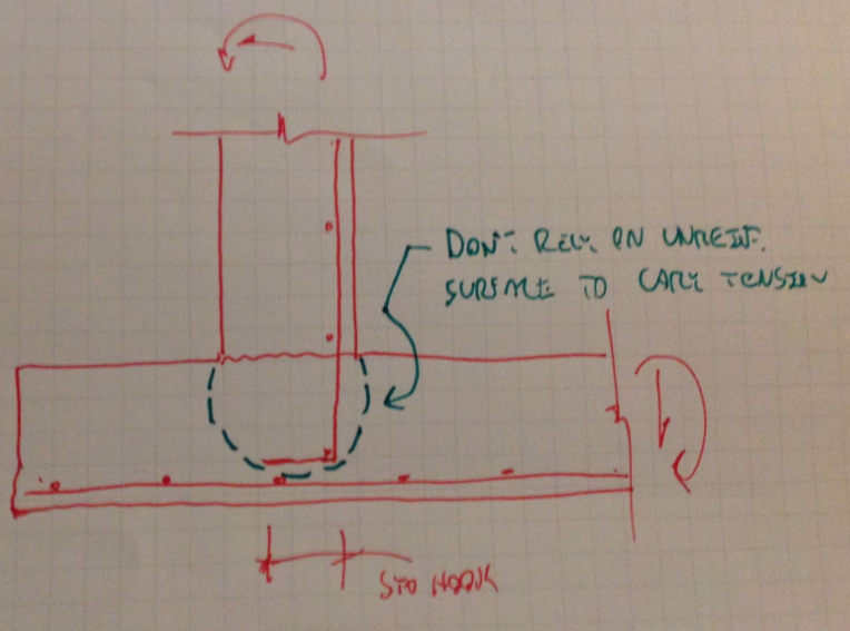
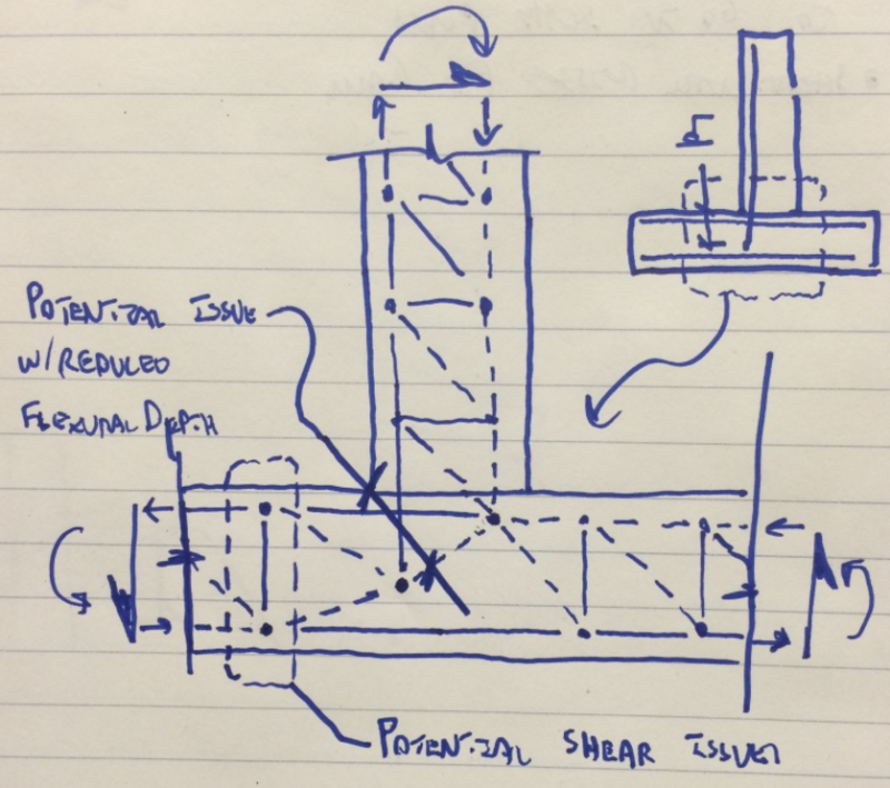
Detail #1 has a version of the problem show below from this document by one of the gods of concrete design. And whether or not the hook sits above or below the bars make no appreciable difference. It's not as though reinforced concrete design is about hanging reinforcing bars from other reinforcing bars. Of course, it's the very same anchorage issue that I highlighted in the STM model that I posted back in March. It would be the concrete breakout potentially represented by those two struts coming up from the hook location.

Capture01_jmjxjy.png


Capture01_vazsto.png


Capture01_tr9emt.png


I like to debate structural engineering theory -- a lot. If I challenge you on something, know that I'm doing so because I respect your opinion enough to either change it or adopt it.
 
KootK said:
There is no link of mine indicating that a standard hook on the stem verts is acceptable. Certainly, that is not what figure 13-28 indicates.

It doesn't dimension it but it's pretty close to a standard hook. It's well short of your requirement "Ld + ???"

KootK said:
Detail #1 has a version of the problem

A slab hanging from a beam is different problem. That being said, only Gilbert would think that slab is going to fall off that beam due to the slab diagonal struts not being anchored up to the top of the beam. I've always wondered that - why are STM proponents so happy to rely on unreinforced concrete to resolve the diagonal tension struts in regular slabs (and beams for that matter). If STM is the new state of the art, and we aren't to rely on unreinforced concrete surfaces, shouldn't we be scrapping all notions of inherent shear capacity? Ties throughout in all slabs from now on?
 
Tomfh said:
It doesn't dimension it but it's pretty close to a standard hook. It's well short of your requirement "Ld + ???"

The intent seems to pretty clearly be extending the corner bars to the end of the toe. With that being the case, the additional bottom bars in the toe become extraneous and lapping requirements would be moot. The prime requirement would be successful anchorage beyond the face of the stem.

Tomfy said:
A slab hanging from a beam is different problem.

It is a different problem but the detailing issue at play is the same: planes of weakness being created where concrete must resist tensile stress for a complete load path.

Tomfh said:
That being said, only Gilbert would think that slab is going to fall off that beam due to the slab diagonal struts not being anchored up to the top of the beam.

While Gilbert's suggestion will lead to better detailing in my opinion, I agree that it shouldn't be strictly necessary. It's probably more important to address hanger bar issues with the stirrups.

Tomfh said:
I've always wondered that - why are STM proponents so happy to rely on unreinforced concrete to resolve the diagonal tension struts in regular slabs (and beams for that matter). If STM is the new state of the art, and we aren't to rely on unreinforced concrete surfaces, shouldn't we be scrapping all notions of inherent shear capacity? Ties throughout in all slabs from now on?

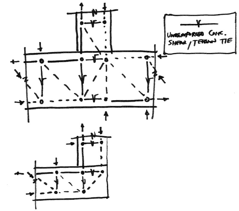
Well, this STM proponent has no intention of abandoning the use of diagonal concrete tension to resist shear. It works and is the most economical solution in many instances. When you're in the Bernoulli region of a member, STM is quite unsuitable as a design tool and really morphs into just a framework for the discussion of how load moves around. To that end, a lot of folks will draw STM models using diagonal concrete tension shear resistance as "phantom" ties. That's what Teguci's done in his model below. Everywhere that you see the SQRT symbol over a tie, it's diagonal tension rather than reinforcing. Sadly, it took me a few months to realize that the SQRT symbol was chosen in homage to SQRT(f'c), the driving parameter behind diagonal tension resistance. Sometimes I'm a little slow on the uptake.

1_cokcwe.jpg


I like to debate structural engineering theory -- a lot. If I challenge you on something, know that I'm doing so because I respect your opinion enough to either change it or adopt it.
 
KootK said:
The intent seems to pretty clearly be extending the corner bars to the end of the toe

It looks fairly close to a normal hook to me, i.e. much the same as your "abominable" detail. The intent behind it being that way makes no difference to how it is.


KootK said:
planes of weakness being created where concrete must resist tensile stress for a complete load path.

KootK said:
this STM proponent has no intention of abandoning the use of diagonal concrete tension to resist shear. It works and is the most economical solution

Why this double standard? Why is the former abominable and the latter perfectly reasonable?
 
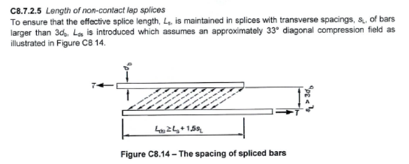
"Am I missing something?" Yes; As the distance of the gap between the bars goes above between 3 to 6 bar diameters, you are not getting the assured stress field transfer you need. The ACI Code (which I openly stated I don't know) apparently treats this by eliminating what I call non-contact lap splices. A lap splice within 3 bar diameters *is* a contact lap splice according to the codes I am familiar with, and only those which need to be extended because of the gap are called "non-contact".

Like so:

Non-Contact_Lap_Splice_obt47f.png


Leading to code clauses like:

Non-Contact_Lap_Splice_Code_Clause_auijng.png


This is the effect that Kootk was talking about, so I presume he said that you hadn't missed something because he is actually familiar with US practice where I am not...

But my fault entirely; I linked the wrong ACI paper and now can't lay my hand on the correct one. *sigh*
 
"The whole point of a hooked anchorage is to quickly develop the tension potential of a reinforcing bar. It would be useless if it didn't apply in tension zones. Most exterior beam column joints have hooked development taking place withing a region of flexural tension and high shear. The reason that the bars need to go around the corner is because the tension force needs to go around the corner. And that's not the same thing as bar development."

No. The way a hook works requires either a compression field or a tension field provided by confinement. That's STM; you can't have it both ways.

Perhaps I could have been more clear, try this: "You can't reliably develop a 90 deg hook in an unreinforced tension or high (unconfined) shear zone." Both are for the same STM reasons; You have to have something to grab onto, and that actually needs to be a compression field, regardless of how it is provided.

I still strongly disagree with your idea that the same force goes around the corner through the bar in all situations. That's frame thinking and doesn't apply to mass concrete, deep beams, or retaining walls. If you have an alternate load path that will result in a lower total stress on the concrete, that is the equilibrium state the concrete and bars will seek.
 
CELinOttawa said:
The ACI Code (which I openly stated I don't know) apparently treats this by eliminating what I call non-contact lap splices

Interesting, yes this nomenclature difference was something I wasn't aware of. I was of course aware that if you exceed the spacing set in codes then you had to consider the compression struts and the resulting increase in development length. In the ACI code this is only allowed if you go to a strut and tie model but there are no "stock" provisions which cover it.

Professional and Structural Engineer (ME, NH, MA)
American Concrete Industries
 
Tomfh said:
The intent behind it being that way makes no difference to how it is.

Huh? The intent behind the detail and the research doesn't affect the conclusions? I'm afraid that I don't follow.

Tomfh said:
Why this double standard? Why is the former abominable and the latter perfectly reasonable?

Firstly, one way shear has been shown to work reliably whereas breakout of concrete anchors (rebar in this case) has not. Are you familiar with the much maligned ACI Appendix D used in the US? It exists because of this problem. The Wheeler research that you keep coming back to intentionally created an environment where concrete breakout would be precluded: mass concrete and stirrups at 125 o/c. As such, that research is not relevant to the concrete in tension issues that are at play here.

Secondly, STM is just one possible method of analysis. Nothing about STM precludes the use of alternate methods that may utilize concrete in tension, particularly in Bernoulli regions. Same goes for folks that are proponents of STM. Being an STM fan doesn't mean that I deny diagonal tension shear resistance.

Tomfh said:
It looks fairly close to a normal hook to me, i.e. much the same as your "abominable" detail.

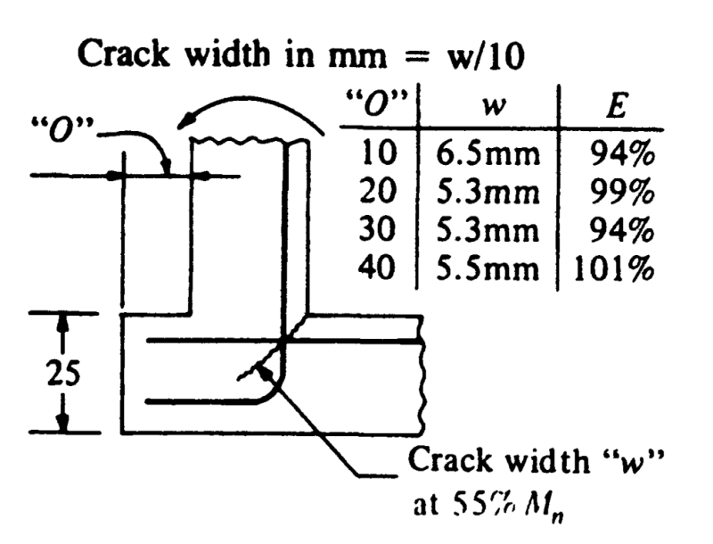
Really? Perhaps look a little closer then. Like most laboratory work, the testing was done on tiny little bars for which a standard hook would be on the order of 120 mm. The tested bars extended out to the end of the toe creating hook extensions ranging from 400 mm to 600 mm.

C01_ahi95i.png


I like to debate structural engineering theory -- a lot. If I challenge you on something, know that I'm doing so because I respect your opinion enough to either change it or adopt it.
 
CELinO said:
This is the effect that Kootk was talking about, so I presume he said that you hadn't missed something because he is actually familiar with US practice where I am not.

Exactly. Our Canadian concrete code is identical of course (below). The only thing that TME may have been missing is that, where the space between lapped bars would exceed 6" or 1/5 lap, a lap extension would be the order of the day. For the bars to be offset that far, spacing would need to exceed 12" which would be rare in my experience.

C01_chudce.png


CELinO said:
I still strongly disagree with your idea that the same force goes around the corner through the bar in all situations. That's frame thinking and doesn't apply to mass concrete, deep beams, or retaining walls.

Oh my. I can see now why we're having trouble finding common ground. The retaining wall joints is absolutely a frame joint and I encourage you to revisit your stance on that. Do you have a access to any of the CRSI handbooks? The shabby sketch that I posted on Jan 14, and have repeated below, illustrates the idea.

Capture01_knk3l0.jpg


I like to debate structural engineering theory -- a lot. If I challenge you on something, know that I'm doing so because I respect your opinion enough to either change it or adopt it.
 
CEL said:
No. The way a hook works requires either a compression field or a tension field provided by confinement. That's STM; you can't have it both ways.

Perhaps I could have been more clear, try this: "You can't reliably develop a 90 deg hook in an unreinforced tension or high (unconfined) shear zone." Both are for the same STM reasons; You have to have something to grab onto, and that actually needs to be a compression field, regardless of how it is provided.

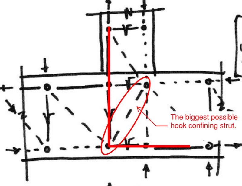
I was confused about your intent. I thought that you meant that you couldn't have a hook in a flexural tension zone. I agree, a hook ought to grab on to a diagonal compression strut. That's a big part of what lead to my confusion. You indicated that you didn't think that the concrete directly below the stem was a good place for a hook. In fact, that is the location where you would have the largest possible compression strut/field available to restrain such a hook. Using corner bars to restrain that monster strut, with properly anchored vertical and horizontal legs, is really the crux of this thread.

Capture_01_aips7e.jpg


I like to debate structural engineering theory -- a lot. If I challenge you on something, know that I'm doing so because I respect your opinion enough to either change it or adopt it.
 
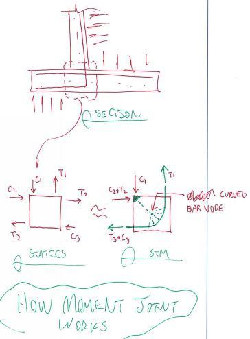
I agree with KootK, the joint from wall base to stem is 100% moment connection joint. Here's a nice little figure from the CRSI retaining wall manual KootK referred to that shows the flexural forces going into this joint:

Capture_ubv3kv.png


This is what KootK is showing with his curved bar node sketch. If possible I highly recommend picking up a copy of the CRSI retaining wall manual (ugh, all broken up into individual manuals now), lots of good info in there.

Professional and Structural Engineer (ME, NH, MA)
American Concrete Industries
www.americanconcrete.com
 
KootK said:
Huh? The intent behind the detail and the research doesn't affect the conclusions?

What I meant was the final geometry and final performance is what it is, and isn't affected by one's intent. What matters is the actual arrangement, and that arrangement with a relatively short extension does not appear to satisfy your critical requirement of Ld + ???. Or does it? If it does satisfy your rules I am happy to stand corrected.

KootK said:
Firstly, one way shear has been shown to work reliably whereas breakout of concrete anchors (rebar in this case) has not.

But where are all these cases of it not working the way we see epoxy bars not work? Why your need to explain away the lack of failures?

If it doesn't work in reality I want to know.

KootK said:
Like most laboratory work, the testing was done on tiny little bars for which a standard hook would be on the order of 120 mm.

Can you provide this research. I am curious to see what they actually did.
 
TME said:
Here's a nice little figure from the CRSI retaining wall manual KootK referred to that shows the flexural forces going into this joint:

Gee that bottom bar's well-anchored isn't it...
 
Tomfh said:
What matters is the actual arrangement, and that arrangement with a relatively short extension does not appear to satisfy your critical requirement of Ld + ???. Or does it? If it does satisfy your rules I am happy to stand corrected.

It does satisfy my "rules". As I mentioned previously,

KootK said:
With that being the case, the additional bottom bars in the toe become extraneous and lapping requirements would be moot. The prime requirement would be successful anchorage beyond the face of the stem.

Tomfh said:
But where are all these cases of it not working the way we see epoxy bars not work?

In the lab, underpinning all the research on joints and anchorage breakout? I don't know man. I'm a practicing engineer, not a curator of the condition of the world's retaining walls.

Tomfh said:
Why your need to explain away the lack of failures?

Uh... because you guys keep asking me to explain away the lack of failures.

Tomfh said:
Can you provide this research. I am curious to see what they actually did.

I cannot. A previous employer had a hard copy; I've never been able to procure a PDF. If you're sufficiently motivated to track down a copy, the source document seems to be this:

Nilsson, I. H. E., and Losberg, A.
“Reinforced Concrete Corners and Joints Subjected to Bending Moment,”
Journal of the Structural Division, ASCE, V. 102, No.

I like to debate structural engineering theory -- a lot. If I challenge you on something, know that I'm doing so because I respect your opinion enough to either change it or adopt it.
 
KootK said:
With that being the case, the additional bottom bars in the toe become extraneous and lapping requirements would be moot

So because it's too short to satisfy your requirements for (Ld + ???) therefore it does actually satisfy your requirement?!?

KootLK said:
Uh... because you guys keep asking me to explain away the lack of failures.

The intention behind pointing out the lack of failures was to illustrate real world performance (or at the very least our impression of it), not to give you something to explain away.

KootK said:
In the lab, underpinning all the research on joints and anchorage breakout?

If you can supply "all the research" showing that regular hooks in the toes have a bad habit of tearing out, I am more than happy to stand corrected and accept it as a detailing abomination.
 
KootK...If you're interested you can obtain a scanned copy of the Nilsson article through the Linda Hall Library (Link).
 
You know those bars that I labelled A & B in my panoply of CEL details above? It works like this:

1) Ld + ??? is about lap splicing the A & B bars.

2) When the B bars extend all the way, the A bars become unnecessary as the B bars cover the flexure every damn place.

3) With the A bars being unnecessary, the lap requirement becomes moot.

I like to debate structural engineering theory -- a lot. If I challenge you on something, know that I'm doing so because I respect your opinion enough to either change it or adopt it.
 
3) With the A bars being unnecessary, the lap requirement becomes moot.

So the anchorage of B stops working once you add the A bars?
 
Deker said:
KootK...If you're interested you can obtain a scanned copy of the Nilsson article through the Linda Hall Library (Link).

Thanks so much Deker. I just might given that:

1) I appear to be doomed, like Sisyphus, to have to defend my position against all comers in perpetuity and;

2) This thread is shaping up to be my personal magnum opus to be left behind to humanity when I pass.

I'm hoping to eventually acquire verb status. Something like: Dude! You really KootK'd the #@%$ outta that joint! I don't even care if it's meant as an aspersion, I just want the notoriety.

Capture01_uxip1z.png


I like to debate structural engineering theory -- a lot. If I challenge you on something, know that I'm doing so because I respect your opinion enough to either change it or adopt it.
 
KootK said:
I appear to be doomed, like Sisyphus, to have to defend my position against all comers in perpetuity

Sisyphus got up the hill.

Show me test results that show a standard hook going into the toe tears up the concrete and I'll happily concede it's an abominable detail.
 
Status
Not open for further replies.

Part and Inventory Search

Sponsor