Continue to Site

Eng-Tips is the largest engineering community on the Internet

Intelligent Work Forums for Engineering Professionals

  • Congratulations waross on being selected by the Eng-Tips community for having the most helpful posts in the forums last week. Way to Go!

Retaining Wall - Flexural Reinforcement from Stem Into Footing 21

Status
Not open for further replies.

CWEngineer

Civil/Environmental
Jul 3, 2002
269
I am trying to get some clarification regarding the flexural reinforcement of the stem of a retaining wall into the footing.

Does the flexural reinforcement in the stem of a wall, need to be developed into the toe, such as show in Figure 1 of the attached document. Or is providing a standard hook (12db), sufficient, such as that show on Figure 2 of the attached document? If providing a standard hook is sufficient, can the hook be turned towards the heel?

Thanks in advance
 
 http://files.engineering.com/getfile.aspx?folder=8fc7a958-bb23-4694-a010-30dca047d4a9&file=Flexural_Reinforcement.pdf
Replies continue below

Recommended for you

Tomfh said:
Yeah but it doesn't work like that in reality. The bar isn't a rope draped over a pulley. It's a sticky bar bend around a sticky surface.

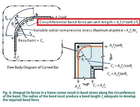
And that very "stickiness" is built into the STM model as circumferential bond force.

Capture3_jgrgfu_sjzto3_sz4gzz.jpg


I like to debate structural engineering theory -- a lot. If I challenge you on something, know that I'm doing so because I respect your opinion enough to either change it or adopt it.
 
Fig 6 is all wrong.

If the applied load and the "exit" load are the same then why are all the internal forces totally assymetric?

Why is there a bond force at all if you're taking it all out via the exit bar?

Why does maximum normal stress occur at the start rather than at the apex?
 
And I still agree with you, in the case where this is a closing moment in a frame.... Just like the Fig 6. title "Unequal tie forces in a frame corner result in bond stress along the circumference of the bend."

So, I think you're still mixing up a force at each side, call it F, with a developed bar, AsFy. In the case of the closing frame moment, we have the two forces, equal and opposite, causing the closing moment. So all of our calcs refer to this as 2x(etc,etc) in terms of the resulting compressive stress. But where we are developing a bar into the footing, we have something more analogous to directly subjecting the inner bend to AsFy.

So: If we consider two forces, or one force closer to AsFy, I think the physics is the same, but the math looks different.
 
CELinO said:
Once we have sufficient concrete around the full development length of the hook, the stresses have been transferred into the surrounding concrete, whether or not the bar then continues or does double duty in the footing. The load path is there, and the stress field will be created, unless you place bond breaking materials.

So... as long as we have developed bars surrounded by concrete, everything will just take care of itself? Seriously? Tell that to all the poor bastards who have been toiling away on the strut and tie method for the last fifty years for, what, their health?

CELinO said:
you cannot decide you don't have a load path when you clearly do.

I have not ignored a load path here. Quite the opposite: I've gone to great pains to actually establish one that can be quantified. The last FBD diagram that you posted is one of the classic offenders with respect to retaining wall joint detailing. Designers think that they can provide a bottom mat independent of the stem bar horizontal projections and, somehow, that obviates the necessity for establishing a mechanism for transfer of moment from the footing to the wall.

I like to debate structural engineering theory -- a lot. If I challenge you on something, know that I'm doing so because I respect your opinion enough to either change it or adopt it.
 
Tom said:
If the applied load and the "exit" load are the same then why are all the internal forces totally assymetric?

Who says they're the same? Certainly not me.

KootK said:
In the general case where entry and exit bar tension is unequal, some force transfer does occur via bond stress.

Tom said:
Why is there a bond force at all if you're taking it all out via the exit bar?

Because, in the general case, you're not taking it all out at the exit bar.

Tom said:
Why does maximum normal stress occur at the start rather than at the apex?

Could go either way depending on the relative proportions I would assume.

I like to debate structural engineering theory -- a lot. If I challenge you on something, know that I'm doing so because I respect your opinion enough to either change it or adopt it.
 
KootK said:
So... as long as we have developed bars surrounded by concrete, everything will just take care of itself? Seriously? Tell that to all the poor bastards who have been toiling away on the strut and tie method for the last fifty years for, what, their health?

The strut and tie method pulls the same sleight of hand. It dissolves the big loads into little circumferential ring tension stresses and then forgets about them.

Sometimes it adds cross bars (e.g. bottle and fan reinforcement) where the trick fails and cracks appear, but it's still sneaking the tension into the concrete.
 
CELinO said:
In the case of the closing frame moment, we have the two forces, equal and opposite, causing the closing moment.

In the case of a common retaining wall, moment must be transferred between the stem and the toe. That moment is equal and opposite and all that jazz... just like with frames.

I like to debate structural engineering theory -- a lot. If I challenge you on something, know that I'm doing so because I respect your opinion enough to either change it or adopt it.
 
KootK said:
Who says they're the same? Certainly not me.

It assumes Asfy load at both bars.

KootK said:
Because, in the general case, you're not taking it all out at the exit bar.

But you said the load doubles? I.e. the load, plus all of it again.

KootK said:
Could go either way depending on the relative proportions I would assume.

You are missing the point. Look at the symmetry (or lack thereof!). If the applied load and exit load are both As.Fy then then the internal forces/vectors should be mirrored about the diagonal. But fig 6. shows one-way bond stress and a triangular normal force diagram!
 
Tomfh said:
The strut and tie method pulls the same sleight of hand. It dissolves the big loads into little circumferential ring tension stresses and then forgets about them.

Not so with the cureved bar node method that has been presented above. The circumferential bond stresses make their way into the radial struts. That's why, at the end of the day, the radial struts usually converge somewhere other than that focal point of the circle.

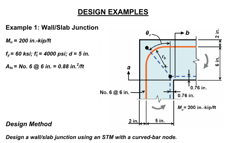
In the Klein document, they cover a slab/wall closing joint as one of the examples. I find it to be quite analagous to the stem / footing joint under consideration here.

Capture_k7iy7v.png


I like to debate structural engineering theory -- a lot. If I challenge you on something, know that I'm doing so because I respect your opinion enough to either change it or adopt it.
 
But again we are conflating two situations... In the case of a seismic frame, for example a beam-column joint, all of those detailing issues are critical. But if we are looking at a uni-directional stress model, we are back to what worked for generations of engineers who did not design reinforced concrete for cyclical loading: Near face corner bars and other "sins", which have little effective harm for such simple load scenarios.

I get the feeling you're trying to fit the retaining wall reality to the STM theory. I think we need a theory which explains the reality, and for more than simply brushing aside the cases you don't like as only being okay because of safety factors and the cautious conservatism of our design codes.
 
KootK said:
Not so with the cureved bar node method that has been presented above. The circumferential bond stresses make their way into the radial struts.

Bond stress = concrete in tension, which neither STM (or any other design method) properly resolves. We just palm it off onto the concrete knowing she's good for it.
 
Tomfh said:
But you said the load doubles? I.e. the load, plus all of it again

Tomfh said:
You are missing the point. Look at the symmetry (or lack thereof!). If the applied load and exit load are both As.Fy then then the internal forces/vectors should be mirrored about the diagonal. But fig 6. shows one-way bond stress and a triangular normal force diagram!

I don't know what to say Tom. I've already clarified, repeatedly and at length, my opinion that 2X is the upper limit and that there is no need for symmetry. Again, from many, many posts back:

KootK said:
In the general case where entry and exit bar tension is unequal, some force transfer does occur via bond stress.

If you're bothered by the asymmetry, that's a Tom issue, not a KootK issue.

I like to debate structural engineering theory -- a lot. If I challenge you on something, know that I'm doing so because I respect your opinion enough to either change it or adopt it.
 
"I find it to be quite analagous to the stem / footing joint under consideration here."

But it isn't. That's a corner, not a slab which is held down and in place away from the joint.

[sarcasm] Next you'll want to be developing bars down into a slab rather than epoxying post-fixed anchors for minor columns. [/sarcasm] There just isn't a need to project the bar further than a competent development where the concrete can take the stress of the loads and resist this as an anchoring beam. That's why I think your continual use of a frame corner is a bad comparison. The frame corner cannot do what the footing is doing...
 
KootK said:
If you're bothered by the asymmetry, that's a Tom issue, not a KootK issue.

KootK, if the load in each bar is As.Fy (as the diagram assert for 45 degrees case) then the internal load vectors have to be symmetric. Think about it.

In particular it is a complete nonsense to say that normal force is maximum at the entry point.
 
On a lighter note - isn't it funny that we can design bridges and buildings and stuff but we can't even agree on what a stupid hook does!
 
Tomfh said:
On a lighter note - isn't it funny that we can design bridges and buildings and stuff but we can't even agree on what a stupid hook does!

It is funny. And telling in my opinion. I think that it's partly a consequence of our over-reliance on computers. We can "design" a building in ETABS in a couple of hours but nobody can detail a joint to save their lives. Of course I do realized that, in your estimation, it's me who cannot design a joint. And that's fine.

I like to debate structural engineering theory -- a lot. If I challenge you on something, know that I'm doing so because I respect your opinion enough to either change it or adopt it.
 
Honestly, I think it just goes to show that the devil is in the details. How many time do we get a project to 90% complete but that last 10% seems to take 90% of the time.

Professional and Structural Engineer (ME, NH, MA)
American Concrete Industries
 
TME said:
Honestly, I think it just goes to show that the devil is in the details. How many time do we get a project to 90% complete but that last 10% seems to take 90% of the time.
100% of the time this is how it goes
 
KootK said:
Of course I do realized that, in your estimation, it's me who cannot design a joint.

I think most of us here can design joints just fine. :)

It's how they really work that we disagree on. I remain fairly convinced a hook doesn't work like Fig.6, despite the fancy vectors and equations.
 
"Of course I do realized that, in your estimation, it's me who cannot design a joint. And that's fine."

Actually I think you can likely design just about any joint you care to, and would to a wonderful job... In my case I just think you're over-thinking this type of joint.

I would love to see some instrumented full scale testing results on retaining walls. I know RMC was doing a bunch of full scale testing on retaining walls some ten years ago, but I think the focus of their work was the pressures in the soil behind the wall. I'll have to do some digging.
 
Status
Not open for further replies.

Part and Inventory Search

Sponsor