Eng-Tips is the largest engineering community on the Internet

Intelligent Work Forums for Engineering Professionals

RFI: References design of thin sheet cladding diaphragms - (EG; PEMB, Industrial portal frames)

Status
Not open for further replies.

human909

Structural
Mar 19, 2018
1,895
0
36
AU
Hi all,

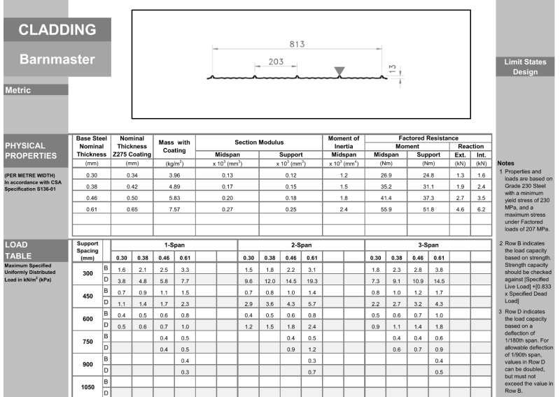
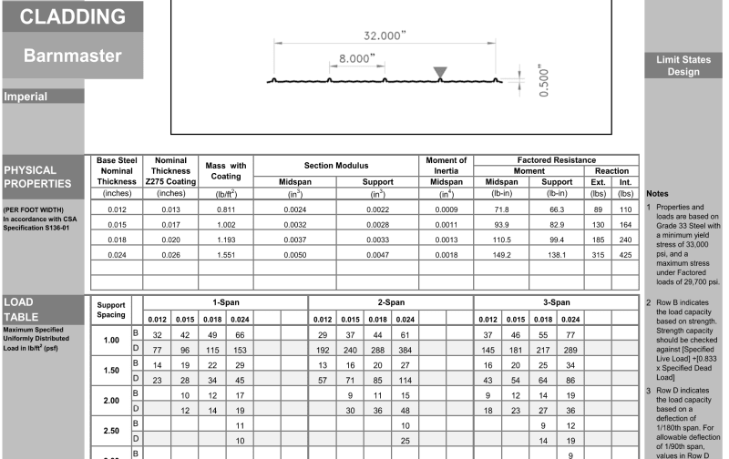
If you have any good references for the behaviour thin sheet (~0.4mm) cladding behaviour for roof/wall diaphragms I'm interest in advice or links. Thanks in advance. [2thumbsup]

(In general I don't consider such cladding as part of my structural load path in my designs. But in reality it does add some stiffness and strength.)
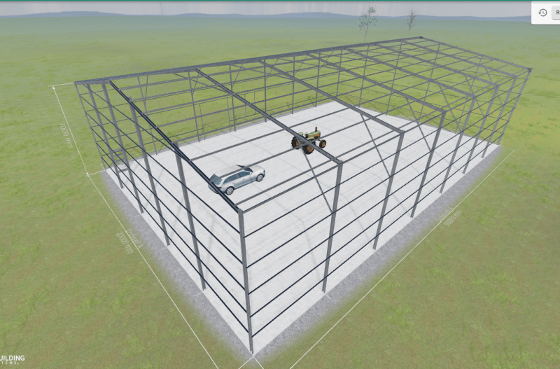
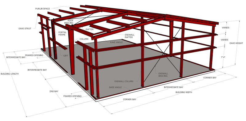
Example structure:
20201103154509-omb-3d-building-2-12-new-001jpg_femvst.jpg


For some background:

I've been tasked with rectifying an particularly under engineered and poorly constructed. "PEMB". I use punctuation around PEMB as in my locality such terminology doesn't really exist but this particularly structure does fit roughly in the North American style of PEMB. This 'shed' is a 20m wide, 7m tall portal frame. It is in Australia and built in a style typical to local construction and to above image, except the columns and rafters are cold formed members rather than hot rolled. It is running at around 2.5 understrength and it's deflection crazy if you don't account for the cladding.

I have free reign to amend the design as appropriate, which could mean conservatively ignoring the influence of the sheeting. But I am curious on what other engineers here are doing and what resources they are using when considering the stiffness and strength of thin cladding.
 
Replies continue below

Recommended for you

i work a fair bit with sheet metal claddings.

generally they are designed to have slip around the fastener holes. as the long run sheets expand and contract with heat, so if they were fixed hard to the structure, they would crinkle/oil-can/ undergo visual distortion, as well as stress the screw fixings.

oversize holes with profiled washers or other slipping mechanisms are typical for these cladding/roofing systems

as such, the diaghram action that these sheets contribute will be effectively nil.
 
Thanks for you response. I appreciate it. But I do respectively disagree.

NorthCivil said:
as such, the diaphragm action that these sheets contribute will be effectively nil
Clad up wall with this and it will stiffen right up. Any backyard/farmyard handy man will tell you this. If you have clad a light frame structure before then you'd have experienced this too. It is pretty damn clear that they DO add significant stiffness and some strength in typical load ranges.

However buckling is of course a big factor and your statement might come close to reality at ultimate limit state loads. But that is what I'm seeking out. Good sources of guidance on this.

NorthCivil said:
generally they are designed to have slip around the fastener holes. as the long run sheets expand and contract with heat, so if they were fixed hard to the structure, they would crinkle/oil-can/ undergo visual distortion, as well as stress the screw fixings.

oversize holes with profiled washers or other slipping mechanisms are typical for these cladding/roofing systems
Slip around faster hole is not what I'm use to on sheets of 0.42mm thickness. Standard here is self tapping screws which are a reasonably rigid connection. Expansion is hardly a problem there is plenty of movement out of plane that relieves this.

NOTE:
I don't disagreed a sensible approach to design is to assume zero stiffness and zero strength. I normally use this approach. However I do recognise that this is conservative and some stiffness and strength exist. There is certainly literature that supports this, but I haven't found the really useful stuff yet.
 
Stressed skin design is dealt with explicitly in Eurocodes (BS EN 1993-1-3 cl10.3 & earlier in BS 5950-9). It gives some analytical and some prescriptive limits.

0.4mm sounds a bit thin but then these may have been tested to verify the performance.
 
My opinion is that if the thin cladding provided one iota of diaphragm capacity, the PEMB designers would be using that. Yet they don't. They provide a separate bracing system, such as rods or angles.
 
I think it boils down to the issue of reliability. Yes, every backyard handyman knows some thin sheet metal will stiffen up a shed...but they also know that a couple nails in a 2x4 cantilevering 6ft will support their lawn mower. Doesn't mean I'd crawl under it...

Best place to find this will probably be with forensic engineers. It's not going to be reliable enough to depend on it to resist design loads (for the reasons NorthCivil stated as well as others), but in retrospect it could certainly be pointed to as a contributing factor to why something didn't fail or why a different failure mode occurred than was predicted when ignoring the sheeting's contribution.
 
JedClampett said:
My opinion is that if the thin cladding provided one iota of diaphragm capacity, the PEMB designers would be using that. Yet they don't. They provide a separate bracing system, such as rods or angles.

I am guessing but it might not be as straightforward as that. For buildability you need to have the underlying frame stable - for a PEMB you wouldn't want to go to the trouble of installing and removing temporary bracing as you might for a hot-rolled frame. For design purposed they might allow quite significant movement and rely on the stressed skin action to stiffen the frame up in the complete building.
 
We see light gauge cladding used as the diaphragm in Pole Buildings (Post Frame) all the time. I am not a fan because I never see the tin fastened in the manner shown in various reports. I found a Thesis on the topic that might be of interest: Aguilera Thesis
 
But those buildings are using 30 gauge or heavier sheet. That's about 7 or 8 times as thick as the OP's question (0.4mm). 30ga is 0.12in thickness, which is about 3mm if I have my conversion right.

Don't mind me...
 
AISI S310 Can be used to evaluate the in plane shear properties of light gage profiled sheets. Its not an easy road to head down. Ideally the diaphragm strength is controlled by the fastener bearing. There are instability failure modes of the panels that need to be evaluated which can be rather complex. There is a wide variety of light gage panels that are used in roofs, some of them are quite capable diaphragms, others are just to keep the rain out.
 
Thanks for the many helpful responses. It does seem like the answer is "you can get something out of it but they failure modes are complex and difficult to accurately determine and is it really worth going down that path."

That is the answer I've assumed previously, but I wanted to dig deeper to see what other peoples experiences and thoughts were. This is a document that addresses sheeting on post frame: But I really haven't found a whole lot of information on a sheet on purlin framing.


JedClampett ( said:
My opinion is that if the thin cladding provided one iota of diaphragm capacity, the PEMB designers would be using that. Yet they don't. They provide a separate bracing system, such as rods or angles.
PEMB do use it around here on the small scale (garden sheds). And even the medium scale (large home sheds) the tiny strap bracing probably is more for erection purposes, the sheeting would be way stiffer and stronger. The PEMB engineer who 'engineered' the building I'm inspecting seems to use it on large portals and the building that I'm looking at isn't the only as per their media profile. But of course that doesn't make it fit for purpose.

In the world of PEMBs here:
Here is a local supplier for example, this was just from a google search. They supply the leading local hardware stores.

And here is some pretty fancy rendering software that makes me a little scared how easy it is on their website:
temp_tt5hyg.png

A 20m x 30m shed.

Of course this is just a rendered image. The final engineering might come out quite differently. I have no reason to believe that this particular company linked is not supplying suitable structures.
 
Again thanks for the responses, and I welcome more. For my own curiosity I wanted to explore this avenue and see what was out there. But I will be signing my name to this in the end and I'm not going to be cutting any corners. I'll be doing something that will allow me to sleep comfortably at night and that any peer review could readily accept as suitable.
 
There has been considerable efforts in the realm of shear walls paneled with profiled steel sheets.

When done well these could make some useful ductile shear walls. Its not much of a stretch for the diaphragm either.

The instability issue is a tough one for me, for the design engineer to get those limits states correct and do it in a reasonable amount of time is a tough pill to swallow. Proprietary research evaluation reports help make this easier but alas most companies who make these panels don't develop these.

Also on heavier buildings I've worked on that use the light gage diaphragm, anchorage into the diaphragm can be

Some research I collected as I endeavored to use these shear walls for a project....

[URL unfurl="true"]https://res.cloudinary.com/engineering-com/image/upload/v1711658571/tips/TR178_Vigh_0_PBU_Panel_Study_irl7ts.pdf[/url]

[URL unfurl="true"]https://res.cloudinary.com/engineering-com/image/upload/v1711658589/tips/yu-et-al-2017-seismic-performance-evaluation-of-cold-formed-steel-shear-walls-using-corrugated-steel-sheathing_f8lr0w.pdf[/url]
 
The Steel Deck Institute has "Diaphragm Design Manual". You can get the third edition for free from them under archived publications.

The Metal Construction Association has "A Primer on Diaphragm Design".

 
We used the cladding for smaller buildings when I designed PEMB almost 30 years ago. The buildings we were willing to use the cladding for were small and there were several different types of custom panel profiles the company produced. We also had a small research and development department. But since then, there have been more regulations here for things being ICC compliant in order to be accepted. You need test data to justify using the panels as lateral resistance if it is a custom panel profile that doesn't already have published values. But I would throw in some cable braces, which are useful to square the building anyway, if this is an occupied building.
 
Status
Not open for further replies.
Back
Top