Eng-Tips is the largest engineering community on the Internet

Intelligent Work Forums for Engineering Professionals

Ridge beam alternative? Structural Framing Help

Status
Not open for further replies.

Niveko

Student
Mar 24, 2024
8
0
0
CA
Hi, thanks to anyone in advance for reading and offering their suggestions, and/or opinions on this particular question. Rudimentary Photos included for clarity.

I am in the process of renovating my parents old house and am trying to re-support certain areas of the home. The house is completely gutted to the framing members, so accessibility is of no concern. The rafter and joists spans are all code compliant. The purpose of this proposition is for load sharing, which is required for details not included, as they will only muddy the waters, and without drawings would be hard to conceptualize.

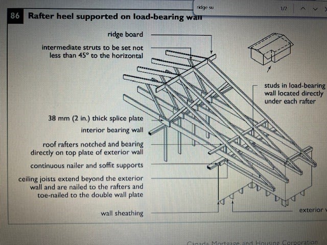
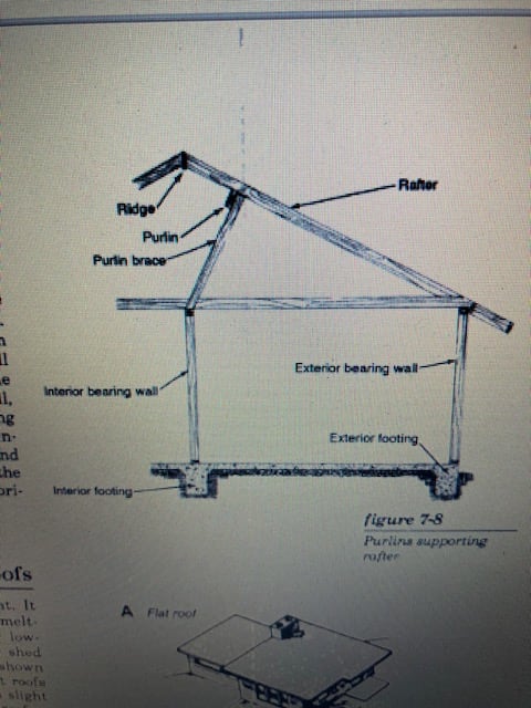
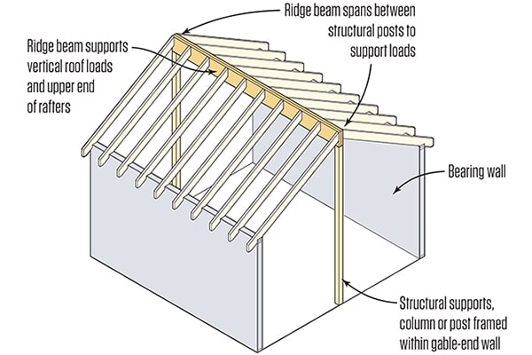
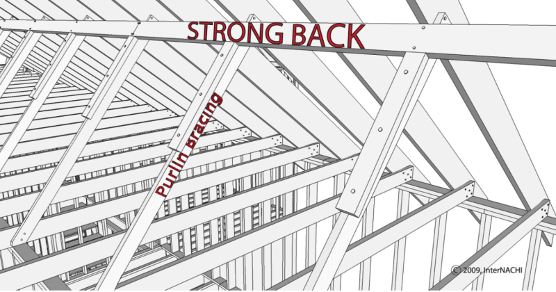
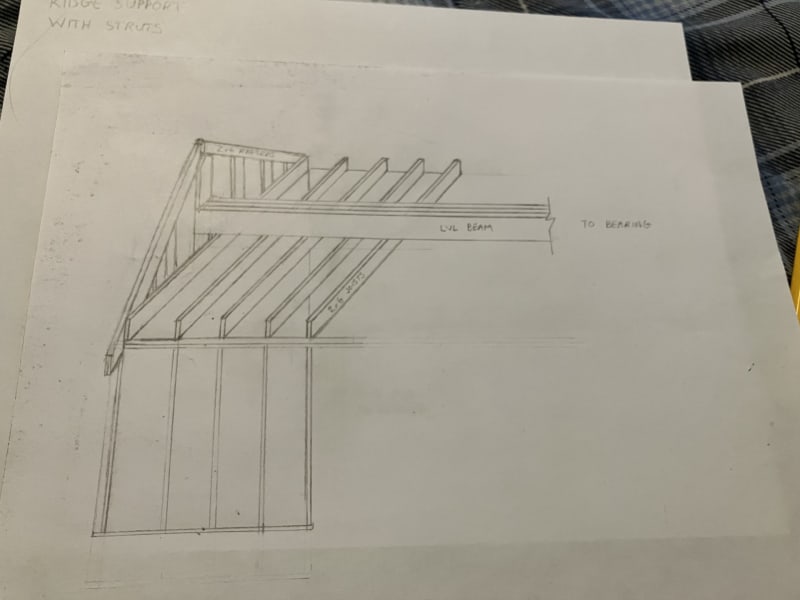
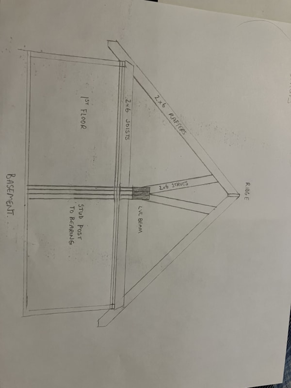
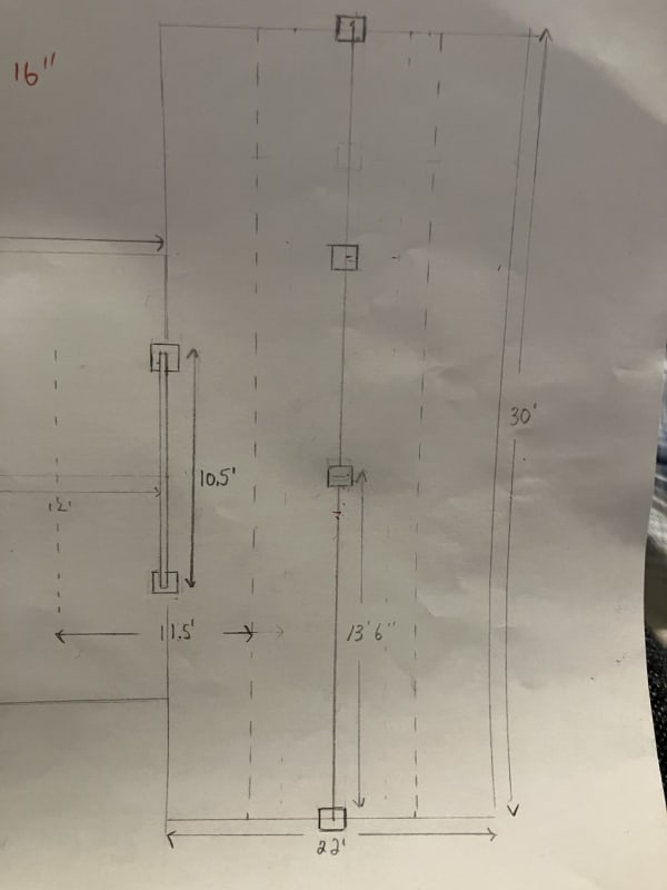
I have had an engineer size the ridge beam (LVL) for this particular area, however, I do not intend to use this as a ridge beam. For me to use this as a ridge beam would suggest that I want a cathedral ceiling in this area, which I do not. I do not have the insulation depth in the roof rafters to satisfy code requirements even if that were the case. Re-framing the roof is not something I want to do. So this is where my question lays, I would like to use this beam in the attic space, raised slightly above the ceiling joists, with framing members (struts) extending upwards at an angle of no more than 45' to support the roof rafters via the purlins and strong backs. The struts extending off the beam will be 2x6's supporting each opposing rafter, 16" O.C at a height/length of about 4 ft. The other option would be to extend a strut vertically to support each opposing rafter. What are the differences in how the load would be shared by the support methods I would like to employ, versus the LVL being in the ridge, as a ridge beam? Would the load transferred to the beam be equal in either scenario? Would it be the tributary area of where my strut lands on the rafter? The tributary area for the strut if it was at a 45' angle to the beam would be about 120 square ft. The bearing points are the same regardless of the placement of the beam. The dimensions of this area is 30 ft x 22 ft. Max Span for the LVL that was sized was 13 ft 6 inches bearing to bearing. If this idea sounds dumb, please explain your reasoning why, lol, or if more information is required please request it.

Ridge_Beam_sv0xsy.jpg


Purlins_and_Struts_ixi5h9.png
[

Beam_above_Ceiling_joists_hgtzut.jpg


Struts_kgmevr.jpg


Area_dimensions_ifpd5n.jpg
 
Replies continue below

Recommended for you

If you're going to put in ceiling joists, they may be able to act as rafter ties. They would need to be adequately connected to the rafters to handle the lateral thrust from the roof, to turn it into a simple truss.

Just go back to the engineer, and clarify that you're not interested in a vaulted/cathedral ceiling, and ask if it can be done with rafter ties instead of the ridge beam. There may be reasons why the ridge beam is the better option, or the rafter tie configuration won't work. It's also possible the engineer may have not understood what you were wanting.
 
Thanks for the reply BridgeSmith,

This area already has rafter ties (ceiling joists), so the need for ridge support by code is unnecessary. This is meant to support the roof to take load off the exterior walls where the rafters and ceiling joists are connected. The engineer at the truss manufacturing building understood what I wanted to do, but said was out of his designing scopes.

I suppose what I consider logical may be misguided as arrogance, and ignorance. That being, if a ridge beam is sized appropriately (spans, deflection, load and support accounted for), which by design would take half the load of the roof, that I can not foresee that the use of it in this particular scenario would cause issues. Numbers prevail though, I understand that
 
Ok, so you want to take load off the exterior walls (why?) and transfer it to an interior wall, rather than columns at the end. Do I have that right? Is there adequate foundation support under the center wall to support half the roof loading?

If the aim is to avoid making modifications to the rafters, why not just put the beam under the ridge, and laterally brace it as necessary?
 
This doesn't make a lot of sense.
Are you required to get an engineer to sign off on the plans?
Is there going to be a building authority inspecting this?
 
Those details are complicated to explain without the aid of photos, but I will do my best. This house has been an addition after an addition. This area is not the original house, the rafters and joists in this particular area are tied into the old gable end of the original house. The bearing beneath this point is a CMU block wall. The block wall that supported the original, old gable end has had modifications (due to renovations throughout home-owner history), that I believe most would consider painful to look at. Portions of this block wall are getting re-done with properly poured and reinforced CMU's to accept what is occurring with supports in the original house separate to the area we are talking about. There is a LVL beam/header going into this old gable end that the rafters and joists that we are discussing are tied into. This LVL beam/header can be sized conservatively if the load is reduced in that wall (due to the rafters tying directing into it). And also, the CMU wall, in general, would be better served if the some of the load could be transferred off of it, to suitable bearing that is achievable in the middle of the house down to existing footings (two exterior walls, one interior block wall, and one pad footing beneath a steel I-beam. There is ample and adequate foundation support.

There is no way of placing the beam directly under the ridge without modification to the rafters due to size of the beam. The rafters would have to be notched with a seta cut and the ridge board would have to reduced in width as well, or all of the rafters shortened with no ridge board as shown in the photo in the first post. Either scenario I don't want to do. I guess the gist of what I'm asking is how can an LVL sized as a ridge beam see any more of a load in the scenario that I'm proposing. All of the connections would be substantial.

The building authority will be in the house at some stage, just not at this moment. I don't cut corners, and I have no intention of concealing work. I just don't have bottomless pockets.
 
I'm a little confused. If there is room enough for the LVL on top of the ceiling joists, why is there not room if it was moved up so that it's positioned directly below the rafters, thereby eliminating the struts between the LVL and the rafters?
 
Ridge_beam_rafter_connection_tflmyp.jpg


There is ample room in the attic space, however, I would have to notch that rafters (approximately 45) as shown in the upper photo of the image attached. The other alternative is shown as well. This beam I believe was minimum 5 1/4 x 9 1/2 x 30 feet long. It just feel like it would be a nightmare to try and get this fit in place perfectly so the rafters are bearing on this. With the strut options, everything is measured and installed tight to the rafter, and tight to the beam. Does this sound crazy?
 
Forgive me for not understanding how that method would be any stronger structurally than what I proposed. There is still a separate member (essentially a collar tie) connecting the loads from rafters to the beam, except your method would have a load path purely through the nails, no? Can you convince me that that is more reliable connection rather than mine where I presume the load can passed through the wood members in contact with one another (ie, like a stud under a top plate), and unable to slide horizontally if installed at an angle due to the notch at the beam end.
 
The configuration I proposed gives you 1.5" x the width of the LVL in bearing without having to notch the rafters. The block would go all the way to to peak, giving you plenty of room for however many nails are needed. If you look at the rafter tie to rafter connections, they're most likely connected with nails in pretty much the same way.
 
Yes in that particular photo it is stated that they are skew nailed, in addition to the strapping that is run over the top and the rafters being in compression against the ridge beam. Those connection details are substantial. I am back into the realm of proving this connection detail is substantial, in addition to being able to transfer the load effectively, so I'm still at square one. For that matter I may as well double the rafters every four feet and 1/2" bolt the triangular block/collar tie. This is demoralizing but what I signed up for.

I also forgot to include that there is a ridge board so that triangular piece would not work it would have to be a horizontal member directly below the ridge board
 
Center_supported_ridge_zqwxpg.jpg
Angled_struts_to_center_support_ycbboi.jpg
Purlin_brace_to_center_bearing_wall_hwacoz.jpg


All of these are examples of how a rafter and ridge are supported, the only difference is I don't want to frame a wall where these supporting members would connect. I dont have a bearing wall in the basement anyways, all I have are 4 bearing points, hence the need for a beam, and having the beam framed beneath the ceiling joists just does not work.
 
Status
Not open for further replies.
Back
Top