Continue to Site

Eng-Tips is the largest engineering community on the Internet

Intelligent Work Forums for Engineering Professionals

  • Congratulations GregLocock on being selected by the Eng-Tips community for having the most helpful posts in the forums last week. Way to Go!

River Pump Power Reduction 1

Status
Not open for further replies.

itsmoked

Electrical
Feb 18, 2005
19,114
Have a river pump with a motor.

The motor is 440vAC, 60hz, 100hp, 134A , 3-phase. rated to output 2,045cubic/meter/min of water.

It's tripping its protection quickly and repeatedly.

It's also delivering 20% more water than expected, (2,454cubic/meter/min).

My take is that the twenty percent is pulling 20% more power hence the trips.
My advice is to restrict the outlet to reduce the mass-flow.

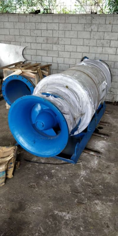
Now seeing the pictures finally, it shows the pump is an axial propeller type. Can I restrict the flow on this type and reduce the loading? Is a propeller a centrifugal pump?
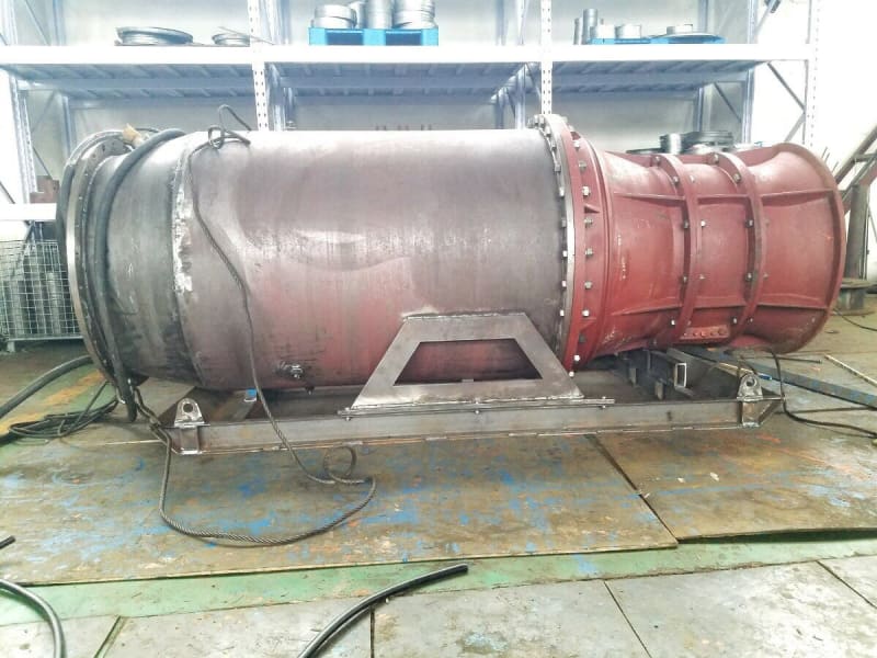
River_pump_side_shot_w28fbx.jpg


River_Pump_inlet_nbjmzb.jpg


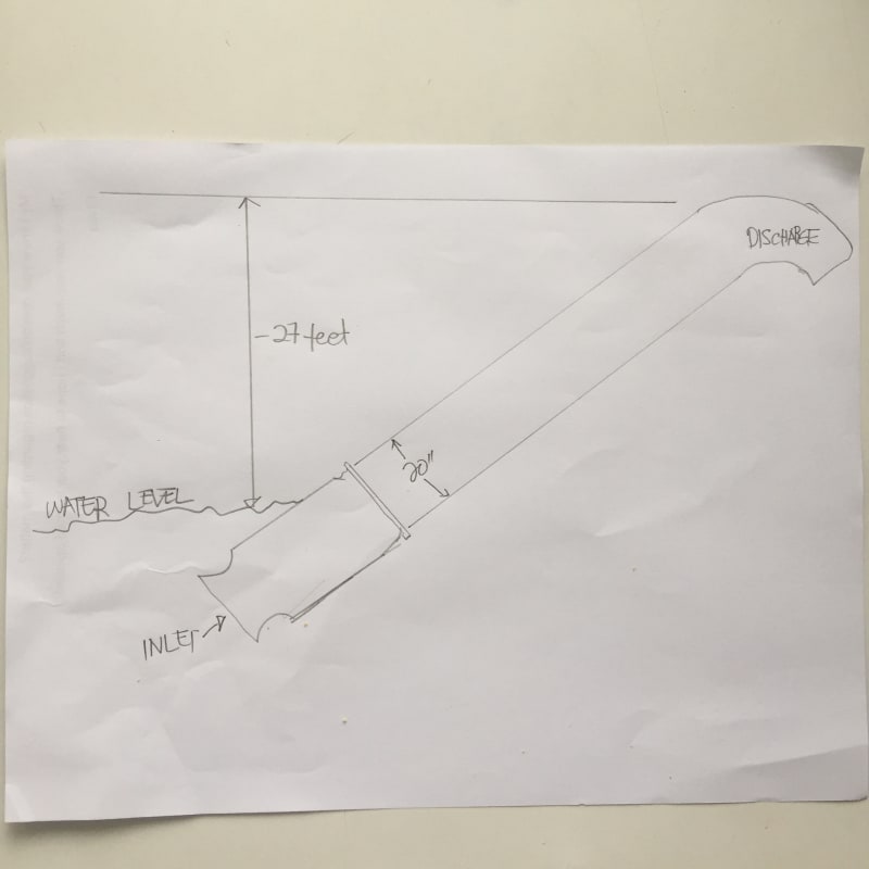
diaghram_ybgx8w.jpg


Keith Cress
kcress -
 
Replies continue below

Recommended for you

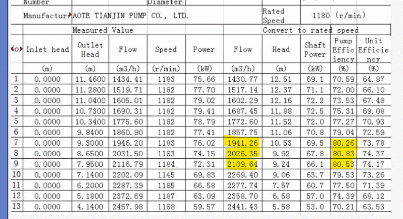
That would have been a good comment in the beginning (I didn't think of that). But it's been overcome by events, we have the table to work with now. And I think ~2,000 m^3 / hr would be the correct interpretation per the table, looking in the middle of the range, where the efficiency is the highest.
Table_fkkelj.gif


=====================================
(2B)+(2B)' ?
 
I'm flummoxed by the data above stating 89hp
I don't see any reference to 89hp, but it would be interesting to know how are we estimating the motor output load level. Was there a current measurement made? Is the overload setpoint known? I'm used to seeing overload setpoint something like 125% of nameplate which would be a current corresponding close to 125hp, but I understand some set it lower like 125% of expected load.... I'm probably missing something. If relying on overload setpoint, have the overloads been checked, are they in a hot ambient, is there repeated starting?

====================================
(2B)+(2B)' ?
 
They're seeing the running current at 172A after which it soon trips the protection.

Their electrician feels they were given a 50Hz motor. They're contemplating a VSD but I'd hate to see them drop the whopping cost of a 100HP drive if the problem is something more fundamental.


My mistake Pete! Doing the math correctly: 74,000W/746 = 100hp

Keith Cress
kcress -
 
I just realised looking at the original post / photo the is a submersible motor unit not a shaft driven unit, therefore a few of my previous comments are not valid [blush][blush][sad].

I see nothing wrong with the test results, note there are 2 sections, 1. as tested and 2. corrected to a constant 1180 rpm, this is normal for a test result.

What has me a little confused now is the final column, "unit efficiency" is this the o/all for inlet to outlet including all pump and motor losses? -- How was the pump tested as a unit or just the turbine?

Keith: suggest you plot a curve base on the corrected speed table - include flow, head and power, then establish what the operating head is from water inlet level to the highest point of the installation, this will assist some what is sorting it out.

Of course it is guaranteed that the unit is running in the correct direction -- usually the first question I ask when coming across a similar site installation problem -- many times I have been assured "yes it is right" only to find out NO it isn't when checked by someone competent -- even more difficult with a pump of this nature once installed - who is going into the river with the crocodiles to check rotation?

I would ask who checked it and how did they check it - plus - do they know which is the correct direction?

It is a capital mistake to theorise before one has data. Insensibly one begins to twist facts to suit theories, instead of theories to suit facts. (Sherlock Holmes - A Scandal in Bohemia.)
 
220 Volts delta at 50 Hz is 380 Volts star.
380 Volts @ 50 Hz x 6/5 V/Hz ratio = 456 Volts @ 60 Hz.
456V/440V = 103.6% This should be usable on 440 Volts.
Following up on Pete's post, how about cutting a hole in the side of the discharge piping and bolting a flanged valve over it to allow an adjustable recirc?
That's a lot cheaper and faster than a VFD.
But first check the voltage and current balances.

[link ]Bill[/url]
--------------------
"Why not the best?"
Jimmy Carter
 
I have to backtrack on my first post which assumed it was an axial flow pump with monotonically decreasing BHP vs flow. We can now see the BHP vs flow pattern looking at the table and it peaks in the middle of the range around 1,687 m^3/hr, and is lower on both sides of that, so it is not monotonically decreasing with flow. This is probably a mixed flow pump, not an axial flow pump. I think there are more stages behind that axial propellor-looking blade you can see in the photo. Maybe others can comment any details of the pump you can deduce from the picture.

I guess from the shape of the table bhp vs flow curve knowing that the measured flow (2500) is far to the right of the peak BHP (which occurs around 1687), then we are in the range where BHP decreases as flow increases so there is still some reason to think Bill's suggestion to try increasing flow might work if it's feasible.

BUT there is still the contradiction in the data that I think Keith was pointing out: Assuming the voltage is somewhere within a few percent of nameplate, then the motor output is somewhere near (Imeasured/Inameplate)*Pnameplate =(172A/134A) * 100hp = 128hp which is far higher than the maximum posssible BHP from the table ~72.5KW=97hp. So something doesn't compute. Wrong pump data table, or wrong voltage or wrong motor data or...


=====================================
(2B)+(2B)' ?
 
The photo shows the impeller, it is just axial, you could argue its mixed flow certainly the bottom end of specific speed for axial, therefore will not perform as a full blown axial impeller.

It is a capital mistake to theorise before one has data. Insensibly one begins to twist facts to suit theories, instead of theories to suit facts. (Sherlock Holmes - A Scandal in Bohemia.)
 
Nothing here makes senses or agrees with each other.

Initial data.
States flow of 2454 m3/HOUR an diagram has a vertical lift of around 8m allowing for the end point of the top of the pipe.
Motor data apparently states 440V 3phase 60htz, 134A 100hp (75kW). But 134A at 440V 3 phase I calculate to be about 98kW. But I will be corrected here as electricity isn't my thing....

Has anyone out there actually confirmed what the running SUPPLY voltage is?

But that pump data sheet....
1) Note the date - 22nd JULY 2020 - they did it yesterday????
2) The change in left hand to right hand doesn't make sense. Left hand rpm is 1182 to 1188. Right hand is 1180.So virtually no change. But look at line 8 - say flow at 2031 - LHS 8.65m @ 74kW. RHS 2026 is now 9.92m@ 67kW. What!!! The flow hardly changes, but the head changes by a significant amount.
3) If we take the RHS as the unit, then at the flow quoted (2454) you only get 5.6m of head (19ft), not the 27 odd feet it is pumping.

Needs some more accurate data / testing to see what exactly is happening here.

Remember - More details = better answers
Also: If you get a response it's polite to respond to it.
 
Hi All,

Here's what I wrote to the gentleman earlier today:
itsmoked said:
Well.. This has been a puzzler. Thank you for the pump curves.
I'm surprised they have yesterday's date on them like the pump curves were tested this Wednesday!??!

We haven't come to any consensus of what the problem is.

China uses 380V 50Hz so if you were actually provided that instead of a 440V/60Hz motor the motor would gain 60/50 x 100HP becoming a 120HP motor without issue.

A typical 440V 120HP motor draws around 150A @ 440V.

You are showing 172A or more...
This brings up the question of if your voltage is not what you think it is? Is it really 440V across all three phases? A difference between phases can cause a LARGE difference in current draw.

Technically when switching between frequencies you want to keep the Volt to Hertz ratio the same as the motor was designed for. Assuming the 380V@50Hz that gives a V/Hz ratio of 380/50 = 7.6
Keeping that same ration shows the voltage should actually be now 60 x 7.6 = 456V not 440V. However, motors typically can take plus or minus 5% voltage which would be 5% x 456V = 22.8V. Which is 456+/-22.8 = 479V to 433V where you say you are. If you're below 433V at the motor this could be a problem.

Is the current the same on all the phases? Sometimes a bad contact in the motor starter can cause a big voltage difference that then causes a bigger yet current imbalance.

Is this a new installation or has it been run before? Sounds like it's a new installation.

His response:

The pump was bought brand new two years ago, but is unused until now, just tested, because of the tripping off from the controllers/limiters due to high amperage.

The supply voltage of 440v from the power company is dependent on the time of the day. The highest is 470v and the lowest is 430v...with 450v just about the most available.

We have other 75hp 440v Centrifugals and all are working fine.

The current on the three lines are within 5-7 amps max. difference, whether up or down.

As I mentioned in my first email, our local electrician is suspecting that the pump we have is not 60hz as contracted but is actually 50hz that is why it is about 20% over its plate amperage capacity rating, though the factory insist it is 60hz. This is a theory given the circumstances.

It is also possible the numbers in the spec plate is not accurate though.

Assuming the specs in the plate is accurate (or not), what do you think is the maximum allowable amperage for long-term operation?

I have seen several times where Chinese companies insist the motor they provide is 60Hz but it was in-fact originally 50Hz. I can see them sleazily insisting that it's a 60Hz motor but only if the voltage is corrected or adjusted to get the V/Hz back into the correct place. Often they'll provide a transformer to make that happen. Technically, they aren't wrong! If the V/Hz is right the motor doesn't care that it's got 20% more HP by way of spinning 20% faster.

I'd expect this 20% more powerful motor to have no problem running this pump since it's load doesn't go up with the cube of the speed like a centrifugal would've.

Keith Cress
kcress -
 
Let's think about this.

A motor calculator states his nameplate 100hp motor should draw 119.8A typically.
But the nameplate FLA is listed as 143A for its 100hp.

This 143A represents a 19% overage likely due to the extra poles (it's a 6 pole motor).

Now if the plate is screwed up cuz some factory yokel only changed the 50hz to 60hz leaving out the fact that it's now 120HP or that the current has to be more at 60Hz what does that possibly get us.

Well the NEW 60Hz 440V 120HP should actually be, using the same calculator, 143A. If we hit it with the same 6-pole 19% surcharge we get 170A. This is what he reports! Of course his protection setup for 143A/100HP is tripping out.

If this logic is correct can the motor whose winding's where expecting 143A take 170A all day long? It is completely immersed in cool water. But, did the original design take that into account and sub-size the wire in the first place?

2hgeq95.gif


Keith Cress
kcress -
 
Great discussion.

I think the motor is tripping essentially because it is over loaded, trip point set at somewhere above 143A close to 170A. i am not mechanically biased, but I do know from the process plant we manage for some clients,that when constant tripping of electric motors are reported, if we confirm that the trip is an over current trip, we advise the process operator to reduce flow after confirming that motor IR is OK. Reducing flow will reduce the work the motor is doing, hence the current. Over current trip could also be as a result of 'wet' motor windings, but unlikely in this case.
So 1. check your windings, do an IR test,.
2.Reduce flow, this should reduce load on motor.
3. You may also want to change protection setting to some value beyond 170A IF AND ONLY IF YOU CAN CONFIRM THAT YOUR MOTOR WINDING TEMPERATURE DOES NOT GO BEYOND ACCEPTABLE VALUE AFTER A PERIOD OF TIME.This is however not usually recommended.
 
Ok, so it's probably not the motir or the voltage, it's the load.

At 170A this motor is giving about 125kW to the load.

Now given that the largest power requirement in the pump table is about 60 to 70 kW for flows> 2000m3/hr there is something seriously adrift here.

Lets go back to flow. The OP says 2450 m3/min.

Could this be 2.45, I e 150 m3/hr??

Is the pump blocked? Branches? Dead cat?

Note that power of axial units climbs a lot as flow decreases. The test only went to 1200m3/hr

The

Remember - More details = better answers
Also: If you get a response it's polite to respond to it.
 
Check motor rotation.

It is a capital mistake to theorise before one has data. Insensibly one begins to twist facts to suit theories, instead of theories to suit facts. (Sherlock Holmes - A Scandal in Bohemia.)
 
Artisi, it's an axial flow pump. If it went backwards it wouldn't pump any water up hill.

If you look at the photo it looks like a screw.

Remember - More details = better answers
Also: If you get a response it's polite to respond to it.
 
LI at the moment we don't know what its pumping and at what head, plus - think sbout a boat propeller driven in a reverse direction.

It is a capital mistake to theorise before one has data. Insensibly one begins to twist facts to suit theories, instead of theories to suit facts. (Sherlock Holmes - A Scandal in Bohemia.)
 
LI, from what little data I can source - it seems that higher specific speed pumps (axial) are unlikely to produce any flow if driven backwards. (just thinking out loud - or maybe not thinking )

It is a capital mistake to theorise before one has data. Insensibly one begins to twist facts to suit theories, instead of theories to suit facts. (Sherlock Holmes - A Scandal in Bohemia.)
 
Basically though the motor is drawing lots more current (about double) than it should given the data provided.

So for me there is something not right with the pump itself.

Remember - More details = better answers
Also: If you get a response it's polite to respond to it.
 
I agree LI. I've provided that to the them and they've gone quiet. Hopefully, while they're trying to get to the bottom of it. Not likely easy with a Chinese company involved. They're battling the same problem we've all been stuck with, that's buying it and putting it on the shelf for a considerable length of time before actually using it, only to have a problem with IT or what was received and subsequently having no leverage with the company to get any help or service since the company knows you can't stop payment or dispute anything financially.

Keith Cress
kcress -
 
Keith,

Did you ever get anything more?

Remember - More details = better answers
Also: If you get a response it's polite to respond to it.
 
Status
Not open for further replies.

Part and Inventory Search

Sponsor