Continue to Site

Eng-Tips is the largest engineering community on the Internet

Intelligent Work Forums for Engineering Professionals

  • Congratulations GregLocock on being selected by the Eng-Tips community for having the most helpful posts in the forums last week. Way to Go!

River Pump Power Reduction 1

Status
Not open for further replies.

itsmoked

Electrical
Feb 18, 2005
19,114
Have a river pump with a motor.

The motor is 440vAC, 60hz, 100hp, 134A , 3-phase. rated to output 2,045cubic/meter/min of water.

It's tripping its protection quickly and repeatedly.

It's also delivering 20% more water than expected, (2,454cubic/meter/min).

My take is that the twenty percent is pulling 20% more power hence the trips.
My advice is to restrict the outlet to reduce the mass-flow.

Now seeing the pictures finally, it shows the pump is an axial propeller type. Can I restrict the flow on this type and reduce the loading? Is a propeller a centrifugal pump?
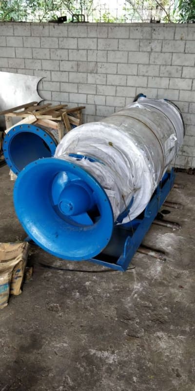
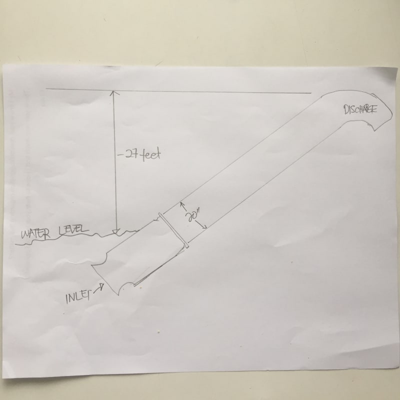
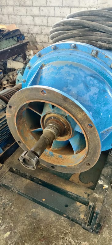
River_pump_side_shot_w28fbx.jpg


River_Pump_inlet_nbjmzb.jpg


diaghram_ybgx8w.jpg


Keith Cress
kcress -
 
Replies continue below

Recommended for you

Just to help with the lay-of-the-land here's some associated photos.
Oh, and they're aware of the rotation requirements and in fact the first bump test was incorrectly clockwise and they promptly reversed it. The pump is a counter-clockwise design and indeed runs counter-clockwise.

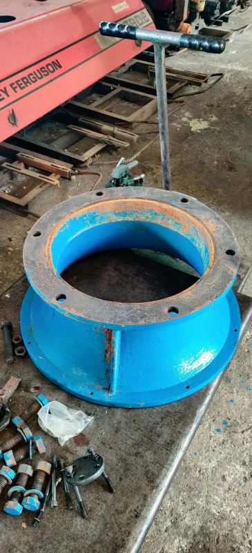
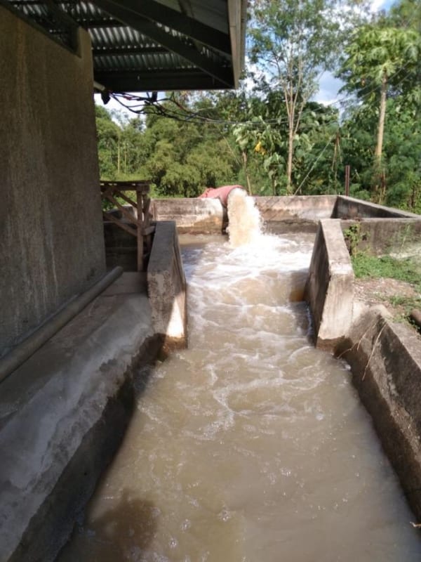
Discharge box
Discharge_Box_x29zpc.jpg


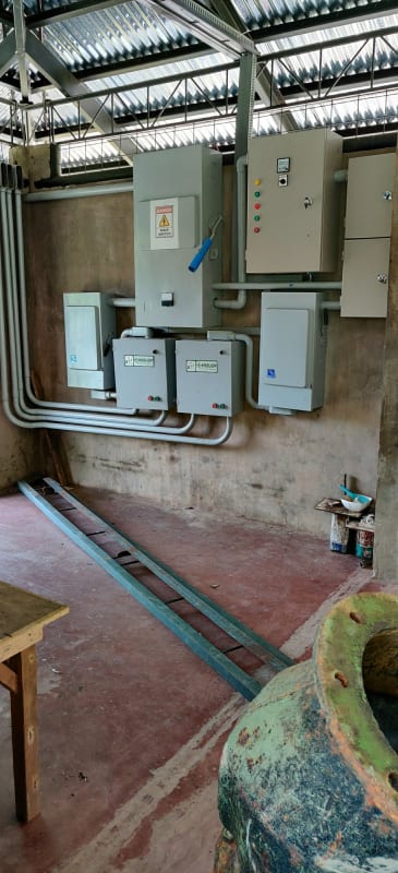
Electrical service. Looks nice!
Power_panels_wp2pk4.jpg


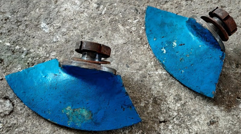
2 of the blades.
two_blades_ekcvmb.jpg


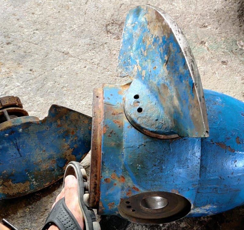
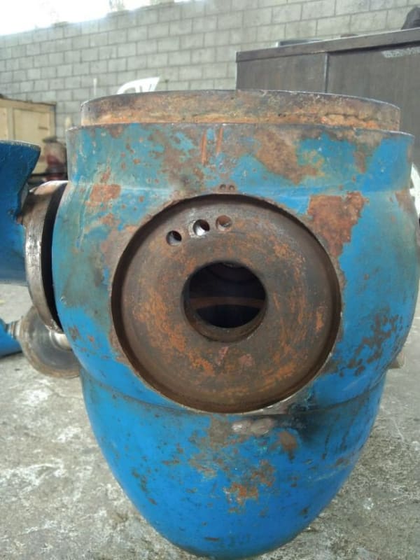
Hub and blades
hub_and_props_mmhtmw.jpg


The duct.
bore_gblewm.jpg


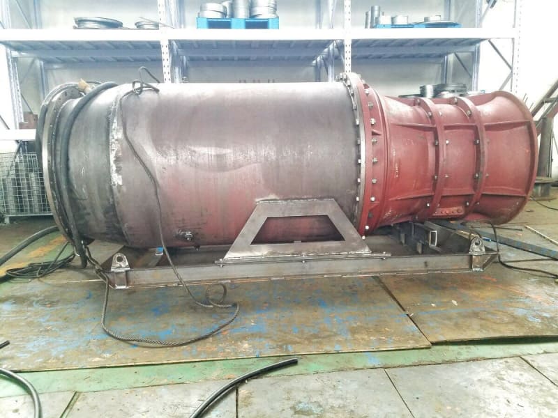
Motor and discharge guide vanes.
The_motor_wkgyb3.jpg


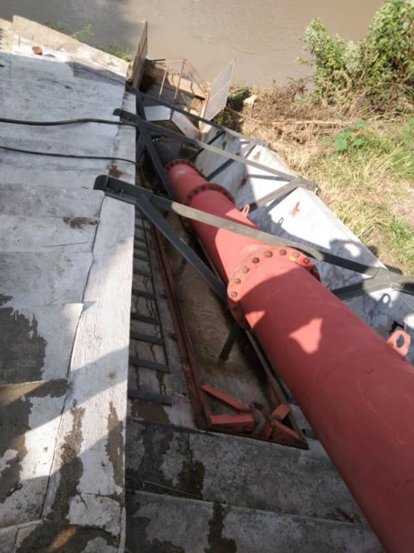
Intake site down a 33° grade.
River_site_palbqw.jpg


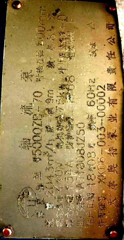
AND something more important. The pump plate!!
Pump_Plate_ma7c5c.jpg


Keith Cress
kcress -
 
Hmm,

Those blades look pretty "agricultural" to me.

Some seem to be a different length than the others? (maybe just an optical illusion but would be good to see all four in a row) and the relationship of the holes to the actual blade angle is rather suspect.

So are they just going to adjust the blades to the minimum pitch and see what happens?

The data plate and the test results are still scrap paper for me. Doesn't literally add up.

Also I like the safety sandals!

Remember - More details = better answers
Also: If you get a response it's polite to respond to it.
 
Keith :
Good the direction is correct, removes one check from the exercise.
Can a check on current draw and speed with a quick dry run be undertaken?
What is the vertical distance from the water level to the highest point, how accurate was the flow measurement that was reported.

Electrics is your area, but assume voltage and everything else is corrrect under operation?

At 2043m3/h @ 9 m WHP is 50Kw
Assume o/a efficiency for pump and motor @ 75% current should be approx. 67Kw, even at 70% o/a- power is still below 75Kw.

Is it a faulty motor - were all 3 phases checked when running?

What I can see on their website, this unit irrespective of blade pitch is under 75Kw.

It is a capital mistake to theorise before one has data. Insensibly one begins to twist facts to suit theories, instead of theories to suit facts. (Sherlock Holmes - A Scandal in Bohemia.)
 
The suction bell does not have locating pins on the flange (6-bolts), and the impeller blades overlap this joint. There is evidence of blade tip rubbing. Assuming the rotor can be easily rotated by hand and that the tip gap is uniform and meets specification (aligned inlet section), then a rub could still occur during operation if resonant vibration was present. The impeller is overhung from the motor bearing, and resonance at shaft speed is possible.

"Strong; as a major pump manufacturer, let us assume in the absence of confirmation, they are capable of supplying 60hz to their test facility."
You say maybe yes and I say maybe no! Perhaps the OEM can confirm if and how it was tested at 60-Hz in a 50-Hz country.

Walt
 
Strong: have you heard of VFD?

It is a capital mistake to theorise before one has data. Insensibly one begins to twist facts to suit theories, instead of theories to suit facts. (Sherlock Holmes - A Scandal in Bohemia.)
 
"Strong: have you heard of VFD?"
Yes I do. Can you confirm that the motor was actually run with a VFD to get from 50-Hz power to 60-Hz excitation?

Walt
 
Getting a bit petty and not much help to the problem.
Can only go on what's been advised, the curve says 1180 rpm - so can you confirm that it wasn't run at 60Hz?

It is a capital mistake to theorise before one has data. Insensibly one begins to twist facts to suit theories, instead of theories to suit facts. (Sherlock Holmes - A Scandal in Bohemia.)
 
Keith, any update?

It is a capital mistake to theorise before one has data. Insensibly one begins to twist facts to suit theories, instead of theories to suit facts. (Sherlock Holmes - A Scandal in Bohemia.)
 
The 'pins' were not what I expected.

I expected that you pulled the pin and moved it from, say, the middle set of holes to the right set of holes changing the blade angle a little in the process.

Nope.

The pin was permanent to the middle hole on one side. I don't recall if it was the hub or the blade, I think the blade. Moving the blade to the right or left holes in the hub moved the blade more than 20° which was way too far.

A machinist was tagged to fill in the holes on the hub and re-drill to provide the factory recommended 4°. I believe they are working on that task at the moment.

Keith Cress
kcress -
 
Keith, I made contact with the manufacturer with a bogus but similar application and asked for pump selection / curve etc. Have now been informed this pump configuration is no longer available. No reason was given as to why - so I tried to lead the conversation for the reason - - - nothing - - was worth a try.
If you can get to somewhere near the required duty, irrespective of speed / vane angle etc, it will be / should be under the 100hp / 75Kw.
Motor speed check?
Interested in hearing your outcome.

It is a capital mistake to theorise before one has data. Insensibly one begins to twist facts to suit theories, instead of theories to suit facts. (Sherlock Holmes - A Scandal in Bohemia.)
 
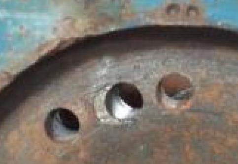
"The pin was permanent to the middle hole on one side." That makes no sense at all. You can see the pin in your pictures. It is a pin in a hole. It may be corroded in place, but obviously it can be removed. What are the the other two holes for? A 20 degree step change in blade angle is obviously useless. If the spacing between the three holes in one part is different than the spacing in the other part, then this is a vernier adjustment of blade pitch. Looking into one of the empty holes in the blade will tell whether it aligns with the hole in the hub, or if the holes are offset. But the pin is not "permanent".
 
The pin may have a taper on the end inside the blade, so it can only be driven out one way (and not the easy way). This is likely because if it does not, the pin could come out of the hole while the pump is running.
 
From middle pin to next one along doesn't look like 20 degrees to me but we don't have a good end on picture of the hub.

If they don't want them to be adjustable why is the option there?

Remember - More details = better answers
Also: If you get a response it's polite to respond to it.
 
Thanks for the try Artisi.

Comp, LI; I could not agree more with you. Having that pin removable and them lined up vernier wise is the only thing that makes sense.

Unfortunately, them being 8k miles away we can only do so much.

Keith Cress
kcress -
 
Keith, any resolution to the problem, would love to know the outcome, good or bad.

It is a capital mistake to theorise before one has data. Insensibly one begins to twist facts to suit theories, instead of theories to suit facts. (Sherlock Holmes - A Scandal in Bohemia.)
 
Maybe I'm completely wrong, and there is a suggestion within this thread that we are looking at two different pumps but to me the photo by Itsmoked dated Aug 9 clearly shows 4 impeller blades, with second photo implying 5 blades. The photo by Itsmoked on Aug 13th shows 6 or 8 blades. So I would suggest that discussions on blade angle and pump curves are somewhat premature until the curve is matched to the actual number of blades.
 
The eight blades are stator blades behind the impeller. It takes the swirl out of the impeller flow to improve pumping efficiency. There does appear to be pictures of both a four and a five blade impeller.
 
Thanks Comp for clarifying that.

Sure there are pictures showing various blade counts because when I asked questions you guys had back to the guy he promptly shot back images, often within minutes, from the Philippines, answering those questions. He could do this by using pictures he already had or of equipment next to him. The answers didn't require a picture of the actual [highlight #3465A4]BLUE[/highlight] prop. There is no confusion about this.

We failed to ever come up with any valid suggestions... Lots of question. No answers. The manufacturer suggested the 4° and while it didn't drop the current down to the exact expected value it dropped it enough to work.

No more discussions are needed as you can see by the movie and the gentleman's satisfaction with the current situation.

Blue for the win!

Keith Cress
kcress -
 
Well they did say 4 degrees would be 12% reduction (didn't say what was 12%.) Current / Power has gone down by 20%.

I can only imagine this is similar to trimming an impellor so lower head and lower flow.

Did he ever measure what the flowrate was compared to previous?

Itsmoked said:
We failed to ever come up with any valid suggestions

BTW I did say earlier
"I suspect that the profile of the blades is different to the test data used and that test data is worthless.
If they want to fix the problem get them to turn the blades to the lowest possible angle. The fact that the test data says nothing about blade angle is also illuminating."

If you can get that much change by a 4 degree change, then it's difficult to see how those blades are machined / fitted to be the same every time. They look like a pretty rough casting to me and or welded onto the hub. Doesn't look like QA is top priority for blade profile and blade angle.

If it wasn't witnessed, then test data is meaningless for any particular pump. IMHO.

Remember - More details = better answers
Also: If you get a response it's polite to respond to it.
 
Status
Not open for further replies.

Part and Inventory Search

Sponsor