Continue to Site

Eng-Tips is the largest engineering community on the Internet

Intelligent Work Forums for Engineering Professionals

  • Congratulations GregLocock on being selected by the Eng-Tips community for having the most helpful posts in the forums last week. Way to Go!

River Pump Power Reduction 1

Status
Not open for further replies.

itsmoked

Electrical
Feb 18, 2005
19,114
Have a river pump with a motor.

The motor is 440vAC, 60hz, 100hp, 134A , 3-phase. rated to output 2,045cubic/meter/min of water.

It's tripping its protection quickly and repeatedly.

It's also delivering 20% more water than expected, (2,454cubic/meter/min).

My take is that the twenty percent is pulling 20% more power hence the trips.
My advice is to restrict the outlet to reduce the mass-flow.

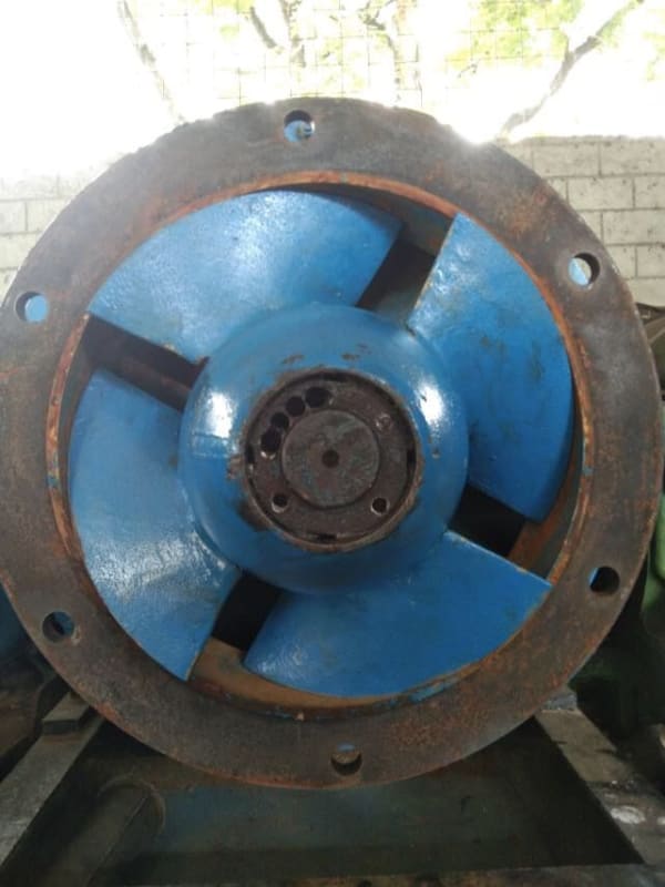
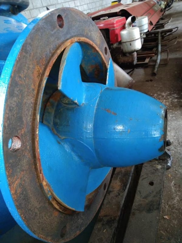
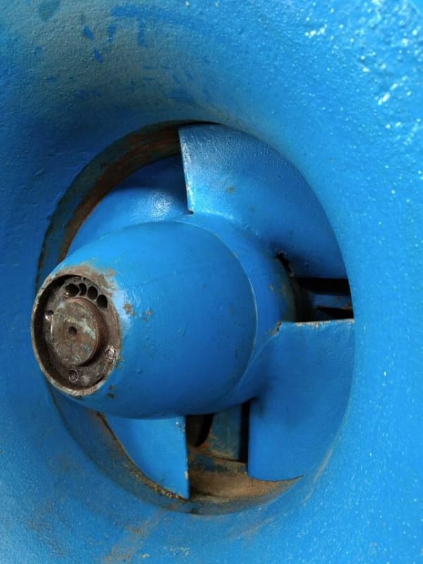
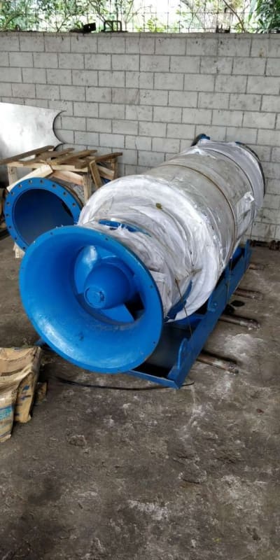
Now seeing the pictures finally, it shows the pump is an axial propeller type. Can I restrict the flow on this type and reduce the loading? Is a propeller a centrifugal pump?
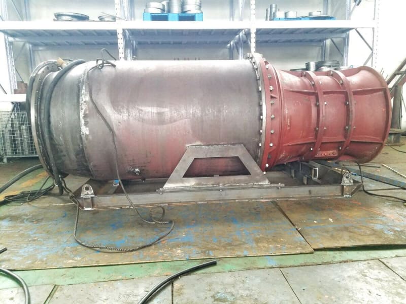
River_pump_side_shot_w28fbx.jpg


River_Pump_inlet_nbjmzb.jpg


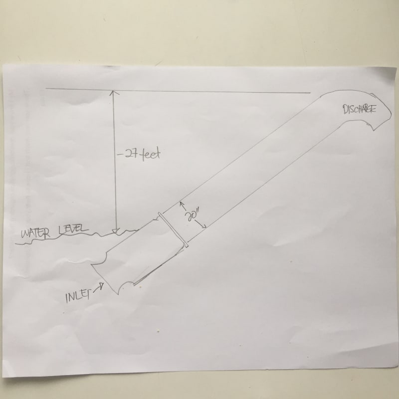
diaghram_ybgx8w.jpg


Keith Cress
kcress -
 
Replies continue below

Recommended for you

If this logic is correct can the motor whose winding's where expecting 143A take 170A all day long? It is completely immersed in cool water. But, did the original design take that into account and sub-size the wire in the first place?
According to this link Table 3, the ratings of Franklin submersible motors is based on assumptions about minimum water flow and maximum water temperature. I would presume other manufacturers would follow the same practice, since not taking credit for water cooling would put them at a cost disadvantage for a given rating.

I'm more familiar with TEAO motors driving fans since we have several at our plant. They use a similar approach.... the rating is based on an assumption about the air flow past the motor. These assumptions are sometimes included on motor nameplate and sometimes buried in the oem documents / literature.

Back to the submersible, if the flow is higher than the minimum assumed flow and/or the water temperature is lower than the maximum assumed temperature that the manufacturer used, then it stands to reason the motor would be capable of operating continously above rated power by some amount, but how much? IF oem's assumptions were known AND actual conditions were known AND we make some big assumptions in order to build a thermal model of the motor, then we might be able to come up with an estimate / swag. But of course OEM input would be best.

=====================================
(2B)+(2B)' ?
 
I think you're correct on this Pete.

Little; I've asked where he's at and will get back with his results for our edification.

Keith Cress
kcress -
 
Putting the test data aside, is it possible that pump was designed for 50 Hz power and speed and put into service with 60 Hz power and speed causing the higher load on the motor?

Walt
 
Strong: the test results are at 60Hz.

It is a capital mistake to theorise before one has data. Insensibly one begins to twist facts to suit theories, instead of theories to suit facts. (Sherlock Holmes - A Scandal in Bohemia.)
 
Okay folks...

Here's where it's at.

River_Pump_2020_08_05T02_34_00_363Z_vfrayl.jpg


River_Pump2_wgbqs0.jpg


River_Pump3_nhwx4w.jpg


River_Pump4_mb2axw.jpg


River_Pumpx_fgr4le.jpg


River_Pumpy_p54772.jpg


River_Pumpz_jojbvt.jpg


The manufacturer informed us the blade angles are adjustable. By reducing the blade pitch by 4° the output will drop by 12% and this should drop the current down.

Does this work for us?


Keith Cress
kcress -
 
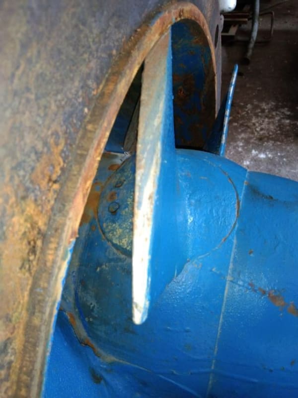
I would be much more concerned with the intended gap or lack of gap between blades and the inlet tube. What is it supposed to be?

Those look like scrape marks to me on the blades.

Only other thing is whether the pump is designed to operate at an angle as shown in one of your sketches above. Is this causing extra friction or bending of the body given the very small gap between blades and body.

Remember - More details = better answers
Also: If you get a response it's polite to respond to it.
 
A lot of corrosion on the bowl ring, enough to cause interference with the impeller blades..as demonstrated by the contact marks on the blades.... whether enough to show up as overload - don't know. Is the pump free to rotate by hand?
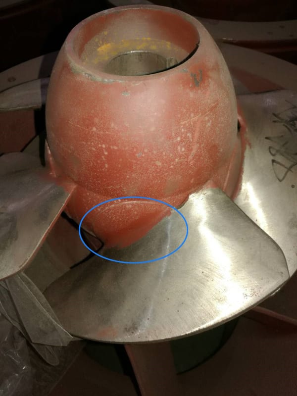
They are showing 2 different impellers, one painted one unpainted is this telling us anything?

It is a capital mistake to theorise before one has data. Insensibly one begins to twist facts to suit theories, instead of theories to suit facts. (Sherlock Holmes - A Scandal in Bohemia.)
 
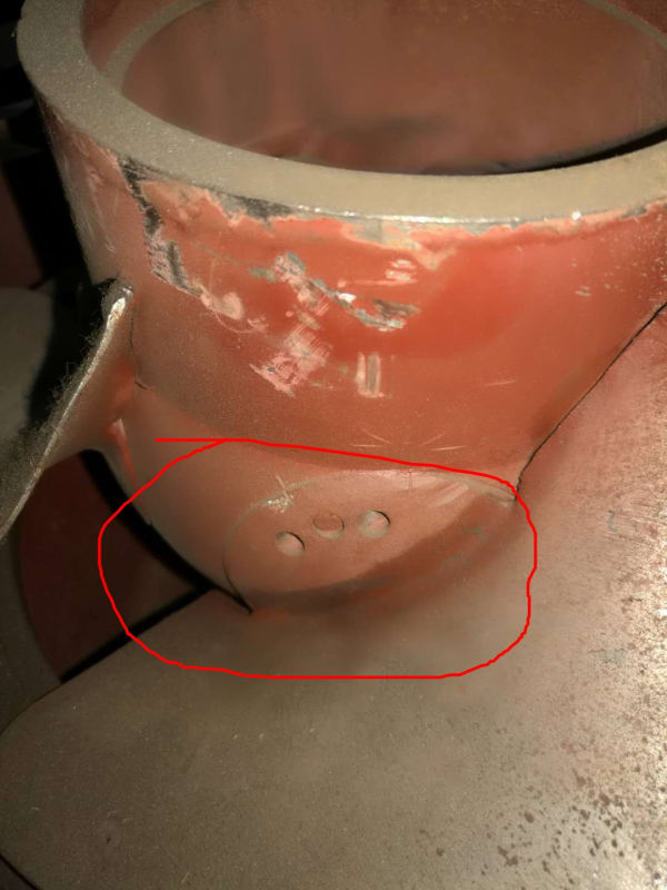
And if the angle change is those two marks on the last photo they look an awful lot more than 4 degrees - more like 40 degrees.

But I agree with artisi, there seem to be photos of different pumps all the time, never the same one.

Also is it my eyesight or does the outer bowl taper in?

Are the blades hitting some of the bowl when it is fully pushed back in the slot?

Remember - More details = better answers
Also: If you get a response it's polite to respond to it.
 
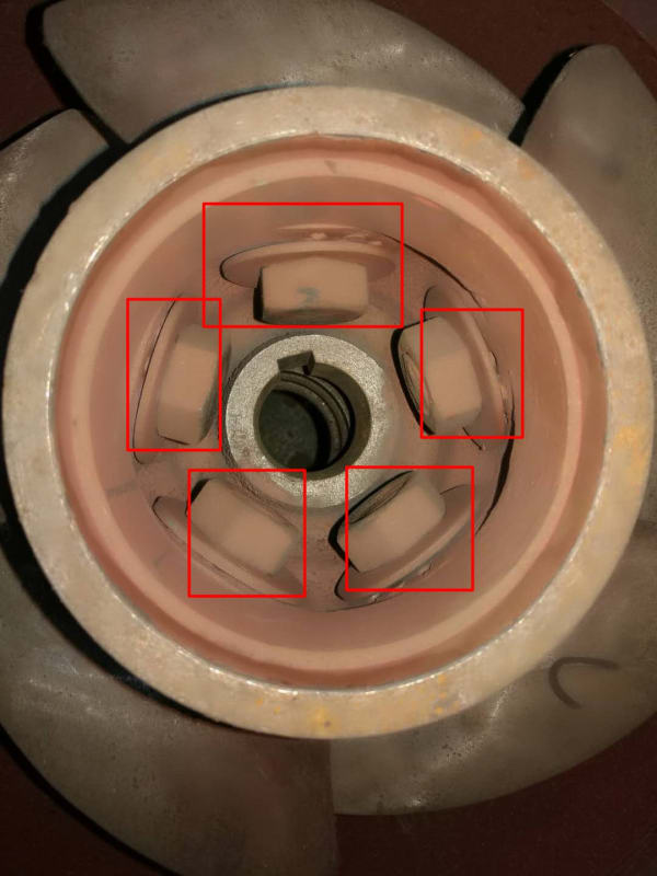
That is two different pumps. The "primed" looking one is in the Chinese factory and are just there to illustrate the setting pins and fasteners involved in a pitch change just sent by the factory.

As for scratch marks... how could there not be any? This thing sits in a river and no doubt pumps sand particles a bazillion times a day cramming them thru the gap.

I'll check to see if it spins freely though the guy seems pretty sharp to me so I doubt a hanging-up blade would escape his notice.

A bending body.. Hmm. I mention that too.

Generally the tighter the gap the more efficient but at some point you certainly would have a fail on getting stuff stuck in the gap.

Yeah seems like a bunch more than 4° for a pin change but since we don't see the pin details it may be the pin holes are a vernier type thing where you pull the pin and move it over a hole in both the prop and the cone. Note there are three holes in the prop and three holes in the cone.

Keith Cress
kcress -
 
Ok I get you. Looks like it's the middle pin at the moment.

For this type of pump I don't think clearance is that crucial to performance but it looks very tight to me both radial and at the back of the bit where the propellor sits.

Those scratches look like metal to metal to me not gravel, but if they are getting bigger pebbles stuck in there and jamming the blades then it will add a lot to the power losses.

A picture of the rIver water would be quite illuminating....

Remember - More details = better answers
Also: If you get a response it's polite to respond to it.
 
Keith, there are thousands of axial flow pumps throughout the world pumping river water, I've seen hundreds of them and the problem of sand / impeller / bowl isn't really a major issue, it accounts for some performance loss but at this stage that's not the problem.
I've had a look thru' their web site and pump data and what I see is that the 100hp,75Kw motor should be ok, marginal maybe but as pointed out, submersible motors can be pushed above what would be a normal "in air rating".

We can assume there is something amiss, it maybe a minor problem, it maybe a major one - - what that is I don't know at this stage.
Can the unit be given s quick run out of the water to establish what the non load power input is? Also check rotation direction and is it correct when installed, to me it's still a thought - I've got a few feelers out with a couple of contacts for commsnt and looking at various avenues for any reference.


It is a capital mistake to theorise before one has data. Insensibly one begins to twist facts to suit theories, instead of theories to suit facts. (Sherlock Holmes - A Scandal in Bohemia.)
 
Keith:
Have received an answer back from the largest manufacturer of axial flow pumps in Australia, they have confirmed my comments that it is possible the high current is from operating the pump with reverse rotation.
This is based on their first hand experience of pumps being run in reverse, they also commented on that axial flow pumps have been and are being run in reverse for aeration of large fish farms.

My suggestion is check direction, certainly not the first time pumps have been connected incorrectly, won't be the last time and certainly not the first time the site sparkie has told you its correct direction.
If the pump is free to rotate by hand, if the power supply is correct I see no reason for it to overload.

It is a capital mistake to theorise before one has data. Insensibly one begins to twist facts to suit theories, instead of theories to suit facts. (Sherlock Holmes - A Scandal in Bohemia.)
 
LI and Artisi; THANKS for the input!

The impeller spins freely by hand. In the river it seems fine with no noises or grinding sounds.

Wow Artisi! Backwards increases the current draw. That's unexpected. I'll pass the word to make sure that's not occurring. Gut feeling is it's the most likely problem as it's so easy to screw that up. A short dry run would prove a lot.

Keith Cress
kcress -
 
Keith:
For any pump way-off performance, the first check is always direction. Who would even guess that 3 wires and 3 termimals could cause so much trouble. Very often a problem on installed pumps after major mechanical or electrical work 😊

It is a capital mistake to theorise before one has data. Insensibly one begins to twist facts to suit theories, instead of theories to suit facts. (Sherlock Holmes - A Scandal in Bohemia.)
 
An open propeller on a tug shaped to favor astern power can only load the engine to 2/3rd of the ahead rating. Most are only 50%. I don't know how being ducted affects that, none of our ducted propellers are reversible.
 
I've gone back and looked at this again and I think the real issue is those test results which simply don't make sense.

Unless there is a lot more, there is no identification of a particular machine, the issue over the date being June 2020, but the pump was bought 2 years ago hasn't been addressed, nor the inconsistencies in the test numbers.

So just taking the figures listed,

RPM 1183, head 9.3m, flow 1946m3/hr, 76 kw. Then conversion to rated speed at 1180 rpm (basically the same speed), magically becomes 1941m3/hr, 10.53m, 69kW. Now to be fair the rated head seems to take into account the fact the pressure guage is 0.9m above the pump but how does it loose 6.5kW?

That second page of results uses numbers not present in the first page.

The data provided about actual lift height and flow is way off the test or rated points so something is seriously wrong (i.e.at measured flow the head is too low, or at stated head the flow is too low). You can't expect a pump to be pumping more flow at a higher head and not using more power.

The only way this pump is going to make sense is to do some testing of it with variable head and flow measurement together with amps.

I suspect that the profile of the blades is different to the test data used and that test data is worthless.

If they want to fix the problem get them to turn the blades to the lowest possible angle. The fact that the test data says nothing about blade angle is also illuminating.

And that's not to mention the discrepancy on the motor data sheet where it states 100hp, but 143A @440 60htz which is about 120hp.

So at the moment, none of the data fits or is actually believable.

Remember - More details = better answers
Also: If you get a response it's polite to respond to it.
 
Itsmoked, for most of them nothing happens. On one of them there is a one way roller clutch in the drive that will break. I have no idea why that clutch is there.
 
Artisi stated: "Strong: the test results are at 60Hz."

Okay, so how did they do test in China with 50-Hz power?

Since we are playing cards with this problem with limited information, so I still say:
The test data is wrong as others have questioned!
The pump and motor were designed for 50-Hz power and operating speed.
Operating pump at higher speed on 60-Hz power causes higher pump load and increased motor current.
Reduce pump load and motor current by reducing impeller blade angle (apparently adjustable).
Verify adequacy of pump performance for the installation.

Walt
 
Strong; as a major pump manufacturer, let us assume in the absence of confirmation, they are capable of supplying 60hz to their test facility.

It is a capital mistake to theorise before one has data. Insensibly one begins to twist facts to suit theories, instead of theories to suit facts. (Sherlock Holmes - A Scandal in Bohemia.)
 
Status
Not open for further replies.

Part and Inventory Search

Sponsor