Continue to Site

Eng-Tips is the largest engineering community on the Internet

Intelligent Work Forums for Engineering Professionals

  • Congratulations KootK on being selected by the Eng-Tips community for having the most helpful posts in the forums last week. Way to Go!

Roof Rafter Collar Tie Calculations/Design 2

Status
Not open for further replies.

mfstructural

Structural
Feb 1, 2009
229
I haven't done a calculation for roof rafters/collar ties in a while and I'm a little rusty. I'm trying to run some calcs on an existing roof that has 2x6 rafters @ 16". The rafters are about 14'-6" in length, roof pitch is 6:12. 2x6 collar tie is located about 30" below the bottom of the ridge board. Previously, these 2x6 members were at the top plate level acting as ceiling joists/rafter ties, but it's been opened up to create an open space. How would I approach this? Does the collar tie reduce the span of the rafter? or do you assume the rafter is spanning the full 14-6"? A 2x6 rafter spanning that far will not work for 25 psf snow and 10 psf DL. I'm not sure how to approach it calculation wise?
Thanks
 
Replies continue below

Recommended for you

Hello,
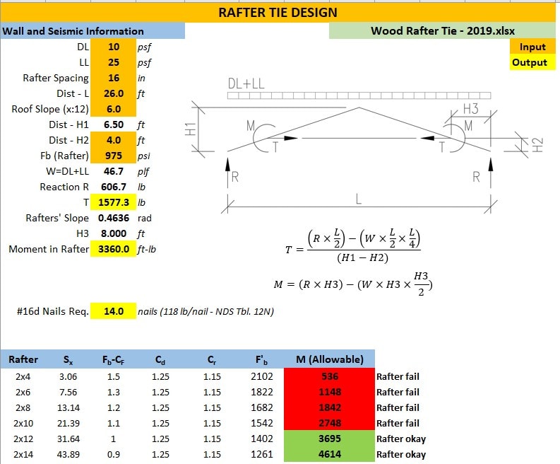
You will have moment in the roof rafters. See the Moment and Tension formulas below. I hope this will help.
Annotation_2019-08-22_101108_xhuq8w.jpg
 
I do these in a 2D frame program as I can easily see the deflection - which seems to control a lot of the cases.
 
To me, the rafter span is unchanged. The tension tie does not support the rafter vertically. It also looks like the tension tie is too high. A collar tie and a tension tie in IRC code terms are different animals.
 
ARPASEVAN's numbers must assume no thrust resistance at the supports, which is conservative. Your hand calcs provide a significant resistance to the horizontal thrust which may or may not be present.
 
JLNJ,
You are correct, I assume no lateral resistance at the supports. (Rafters sitting over stud wall with no out of plane resistance @ top)
 
JLNJ,
What field conditions would constitute significant resistance to horizontal thrust? In my case there is an 8' wall with rafters bearing on. I don't think that has much out of plane resistance. So basically my calcs show that the connection between the bottom of the roof rafter and top of the wall has to transfer that load. In other words, the cantilevered wall has to resist that thrust?
 
The walls can not resist thrust through cantilever action. And Typically, truss action is not effective in this setup unless the tension tie is located either at the wall plate or very close to it. The only way your system to work with the current location of the truss tie is using a stronger/stiffer rafters, probably a 2x10 or 2x12, possibly an LVL. The tie to rafter connection also has to be very robust. As others have mentioned, horizontal deflection at the top of the is a concern, I believe the truss plate institute limits it to 1.25” at the top of the wall. Another solution may be to use a deep glulam structural ridge beam to act as an interior support at the ridge and remove the need for the tension tie. This is often done with fully vaulted ceilings for spans up to 30 feet or so.
 
I do not know what you are calling a "cantilevered wall" but a fixed base wall could resist thrust to some degree. What are you calling a cantilevered wall?
 
Unless the walls are not wide and you can get some benefit from the top plate stiffness, there is technically no horizontal resistance available.
I can't stress enough that you NEED to check deflection as it will most likely control.
 
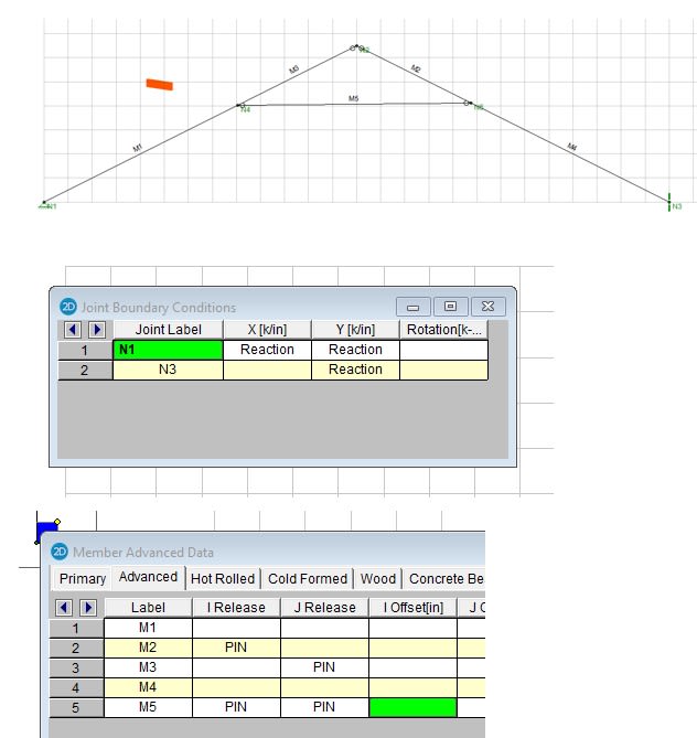
The walls I'm dealing with are 2x4 walls. They're anchored to the foundation but I don't count on that to provide any out of plane resistance. So basically, we need the collar tie and rafters to resist all the thrust. I created a model, but am getting an instability issue. I have all the ends of the members set as pinned and the supports are pinned. See attached screenshot. Any idea why I'm getting this error?
 
 https://files.engineering.com/getfile.aspx?folder=fc21f104-c26d-46f8-9949-a6de47ad07f2&file=frame.jpg
either N5 or N1 needs to be a roller, otherwise you haven't satisfied this
..but I don't count on that to provide any out of plane resistance...

You also cannot pin members at a support location if only one member frames to it, the support provides the member end releases

N3 pin only one of the members at that node

assume at N2 and N4 only the tie has pins defined, you may also consider setting the tie as a tension only member.

If it runs with those parameters review the shear, moment, and axial diagrams to make sure those make sense.

Open Source Structural Applications:
 
I made one of the supports a pin and fixed all the rafters except the end of one member at the ridge. The two ends of the collar tie are pinned and I'm still getting an instability. The error says "inadequate restraint. Check Boundary Conditions. The model is currently unstable." This shouldn't be the case as the frame should resist the forces and not just deflect indefinitely, right?
 
mfstructural,model it as shown below and you will not get the instability error.

Annotation_2019-08-23_142634_q8qjcs.jpg
 
I'm a little confused as I'm still getting the instability error? Am I missing something?
I have it pinned correctly and also added boundary conditions to be fixed in z direction (out of plane). I attached screenshot. Any thoughts?
 
 https://files.engineering.com/getfile.aspx?folder=3a6e0412-bab6-4520-9539-fd1af98d8bd0&file=Frame_R1.jpg
Using the geometry shown by ARPASEVAN:

w = 46.7 plf
R[sub]1[/sub] = R[sub]5[/sub] = 26(46.7)/2 = 607.1#
H[sub]1[/sub] = H[sub]5[/sub] = 0 (horizontal force = zero if Node 5 is a roller).

M[sub]2[/sub] = 607.1*8 - 46.7(8)[sup]2[/sup]/2 = 4856.8 - 1494.4 = 3,362'#

The reaction and rafter moment agree closely with the ARPASEVAN result.
Not much point checking deflection as a 2x6 rafter cannot sustain M[sub]2[/sub]


BA
 
Uninteresting that none of the comments above consider the effect of roof plywood sheathing providing a beam effect within the plane of the roof sides. Unknown safety factor I guess.
 
Plywood sheathing by itself is not reliable as a beam. Plywood sheathing, properly nailed, combined with a continuous chord member along the eave could provide beam action. Farm buildings have been constructed on that principle but engineered structures usually do not rely on that behavior because of the special and continuous inspection required to ensure reliable performance.

BA
 
Status
Not open for further replies.

Part and Inventory Search

Sponsor