Continue to Site

Eng-Tips is the largest engineering community on the Internet

Intelligent Work Forums for Engineering Professionals

  • Congratulations KootK on being selected by the Eng-Tips community for having the most helpful posts in the forums last week. Way to Go!

Rotation ability for shear end plate connection 6

Status
Not open for further replies.

TTTKAO

Mining
Aug 24, 2022
78
Hello all,

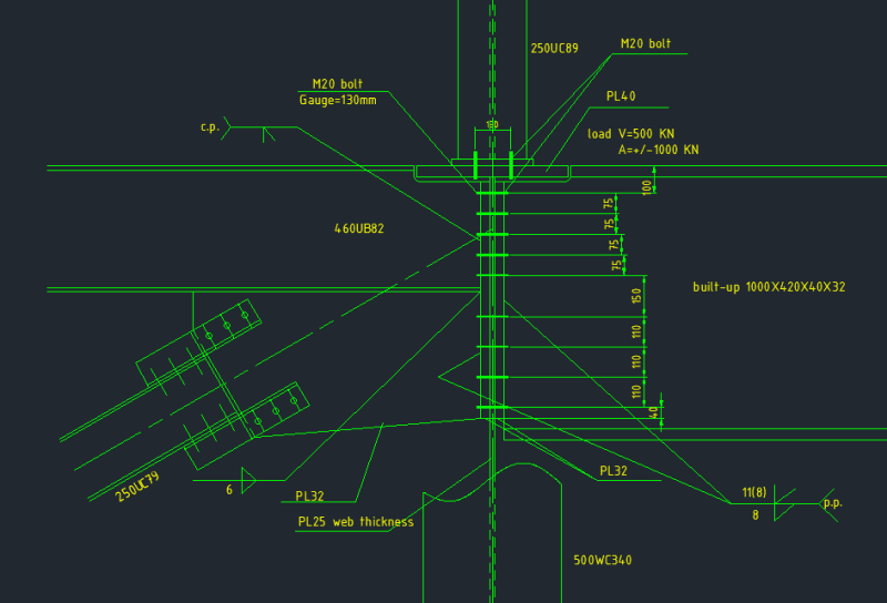
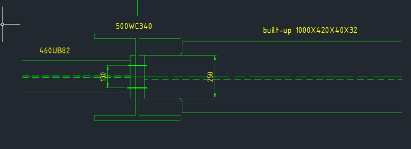
i am working on a girder beam(1000X420X40X32) to column web(25mm) connection with a big shear load(500KN) and transfer load(+/- 1000KN). i am using shear end plate (32mm) to transfer the load. a very thick endplate needed after considering prying action( M20 steel bolt is used). I have a little concern about the rotation ability for the girder beam as the end plate is too thick.it may become a semi-rigid connection which can take some moment which i don't expect to see. but from another side it seems impossible to use a thin end plate due to the heavy section and big design load. i am wondering who can give some suggestion and opinions for this detail? i attached the detail for detail information. and are there any good articles addressing end plate connection rotation ability?

thank you!
2_ru15vm.png
1_xd8wkc.png
 
Replies continue below

Recommended for you


Thank you so much for the sketch. it's hard for me to meet this situation.
 

HI Human909,

Thank you so much for the sharing.


What fails? Is it an actual failure? Or just a code failure. You say AISC DG-16, design guides are normally just that. Guides. You as an engineer can decide to ignore 'failed' results.

yes I agreed, engineer need make a decision as per the situation by the analysis.

If it is a brittle failure then it might be something to worry about, if it is a ductile failure mode or simply a design guide failure then it probably isn't an issue. Also if you dug deep you might find your 50% moment is way too high. You could consider a 50% of the moment capacity of the web and forget the flanges. Most likely the connection will be 'fine' but demonstrating that is the case can be the harder part.

May I ask how to get" 50% of the moment capacity of the web and forget the flanges" do you mean assume the rotation is around bottom bolt row, not rotate around bottom flange?

I recently had a vaguely similar situation with short members and relatively high loads. I couldn't easily achieve a pinned connection without introducing excessive eccentricity and torsion on the primary beam. I ended up designing flush end plate (semi) rigid connection, any torsion on the primary beam was then compatibility torsion and thus limited.

I have similar connections to this one in other places, but my situation is the supported beam has a relative large axial load comparing to shear load. as the supporting beam is not good to resist torsion and the flush end plate can help to restrain supporting beam flanges, this connection is better than extend plate connection if torsion is a critical concern.

I say semi-rigid because according to my relevant code and recommended design guides it didn't pass the recommended requirements for a fully rigid connection. But the connection was still more than strong enough for the full moment even though it was probably only 60% of the stiffness of a fully rigid connection.


It's a lot easier if you can, and avoids your moment issue, and is likely less costly.

-----*****-----
So strange to see the singularity approaching while the entire planet is rapidly turning into a hellscape. -John Coates

-Dik
 
I suspect your current connection is quite suitable but I don't have the full details to support that argument.

Dik's suggestion of a bearing connection is great for shear but is almost certainly insufficient for the axial load. The knee brace is also a bad idea for reasons Italo01 explained. DrZoidberWoop nailed it, this is an excellent solution for transferring axial load, don't reinvent the wheel.

ArcherC said:
the full rigid moment here is around 2200KN*m as per analysis
How are you coming up with this figure? Is this with a rigid end restraint on the beam or with the actual modelled 500WC340?

ArcherC said:
May I ask how to get" 50% of the moment capacity of the web and forget the flanges" do you mean assume the rotation is around bottom bolt row, not rotate around bottom flange?
Well you flanges aren't being engaged and your top flange is completely removed. The capacity of the web to transmit moment is significantly reduced.

(Though that in itself can occasionally be an issue, in my example I referred to early I could cope both flanges to achieve a pinned connection but the web failed in moment due to the excessive coping.)
 
I didn't notice the axial load... not a good connection.

-----*****-----
So strange to see the singularity approaching while the entire planet is rapidly turning into a hellscape. -John Coates

-Dik
 
human909 said:
Dik's suggestion of a bearing connection is great for shear but is almost certainly insufficient for the axial load. The knee brace is also a bad idea for reasons Italo01 explained. DrZoidberWoop nailed it, this is an excellent solution for transferring axial load, don't reinvent the wheel.

Hi Human909,
Sorry for the late reply. Thank you again for the suggestion. I agree with all concepts from Dik,Italo01,DrZoidberWoop.. just have some different understandings also based on these concepts.

For the without Knee brace option: I used this kind connection to transfer axial before , but for the heavy girder beams with heavy end plate at critical location, it's my first time to use it. as it's hard to estimate the moment it will attract in reality. that's why i am struggling. wondering if we are still confident to use it for heavy section or we may do some upgrade.

For the knee brace option: I figured out this one due to the concern above which may be safer i think or kinds of double protection for this joint. actually, i will use a heavy knee brace section 250mm/300mm column section. this combined joint is more rigid than without knee brace option and will attract more moment for this joint. but this moment is provided by girder tension and knee brace compression(take gravity moment for example),and won't increase girder moment that's the reason i figure out this option. we may limit the girder end moment in reality under control by use of this. but for this option, i am not sure are there any others issued i didn't notice...

Thank you.


The knee brace "option" may not be 'safer' it puts loads on the column in a location that is less than ideal to take loads. It could fail the column. But that can't be determined without further information.

ArcherC said:
"it's hard to estimate the moment it will attract in reality."
Yes it is. But sometimes engineers need to do the hard stuff.

You need to provide more detail if you want more assistance. If you are designing the connection without context of the entire beam and structure that makes things difficult and it one of the reasons why I've always found it absurd to separate connection design from member and structure design.

If you are only designing the connection then I'd go back to the engineer and get more information about the structure. Because the stiffness of the structure really matters here. As I've said multiple times there is probably sufficient flexibility in the connection and the column that means the moment is reduced considerably. But that cannot be determined without knowing more about the structure.
 
human909 said:
You need to provide more detail if you want more assistance. If you are designing the connection without context of the entire beam and structure that makes things difficult and it one of the reasons why I've always found it absurd to separate connection design from member and structure design.

Hi Human909,
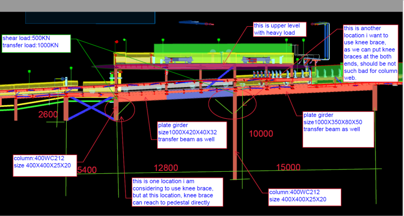
I totally agree, the connection need to be designed with considering the whole structure. i am the engineer as well. i attached the bay of the structure with dimensions. let me know if you want to see more information.

thank you so much for the assistance again.

Regards!
4_tlukjm.png
 
Good morning All,

I am wondering if anyone has opinion or preference for the without brace option and braced option?

at the same time, i have another question, for the 10m column , i can rotate it 90 degree, in this way the girder will connect to column flange directly, Does it will help load transfer ?

Thank you.
 
I remains unclear about what you want to achieve. You seem to be struggling to design a suitable pinned connection to your satisfaction and are instead choosing to add members (knee braces) to change the structural behaviour to avoid having to design the simple pin connection.

You either need to figure this out yourself or provide EXTENSIVE information on what loads, what combinations and what you are having difficulty achieving. From where I sit the original connection seems mostly suitable.

human909 said:
the full rigid moment here is around 2200KN*m as per analysis
Again. How are you coming up with this figure? A quick analysis of your system with the available information doesn't produce moments at the WC connection anywhere near this amount.
 
Good morning human909 and all ,

human909 said:
You seem to be struggling to design a suitable pinned connection to your satisfaction and are instead choosing to add members (knee braces) to change the structural behaviour to avoid having to design the simple pin connection.
I consult a few engineers within my team these days, the common agreement is adding knee won't help a lot to release my concern but make assumption more complicated. same as yours.. the without knee brace should be the proper solution here, i will consider some reasonable moment this end plate will attract, i have some ideas regrading to how to consider it, and will post here after i get a number. and 2200KN*m moment is an extremely number from fully moment connection set in analysis model. won't happen in reality.

i have another item want to get some opinions as well. for the end plate connection without braces. i am thinking if i should extend end plate to bottom flange of girder or not ?
The advantage of this is "girder web plate will have less yielding concern as the girder only coped at top flange"
The disadvantage of this is" it will attract more moment by connection to bottom flange"
DrZoidberWoop said:
Your original connection is commonly accepted for this scenario. It has some ability to attract moment, but opposing end-plates are one of the best methods to transfer axial loads through column webs. We're obviously working with different codes, but you can make the original detail work just fine. Steel is fun because you can control the load path by sizing your welds/connecting-elements. That will draw the axial load in certain proportions to the desired elements.
May i ask what did you do before , extending end plate to bottom flange or not ?

Thank you so much again for all your time, opinion and explanation.

Regards!


I don't see what you expect to achieve by extending the end plate to the flangem you are only going to get a stiffer connection that attracts a little more moment.

Regarding the moment I'd just start by modelling it as a totally rigid connection to the column and take that as your upper limit. My result from.memory was less than 10% of you 2200kN figure.

I personally would consider a simple welded shear cleat. It would be fine in shear and axial load will giving less rational stiffness compared to the end plate. (Though given the depth even these connections start to behave in a semi rigid fashion.)

Also consider making your connection not full depth whether you go with an end plate or a shear cleat you don't need the full 1000 depth for those loads consider a 60% deep connection. This will considerable increase the connection flexibility.
 
ArcherC said:
May i ask what did you do before , extending end plate to bottom flange or not ?

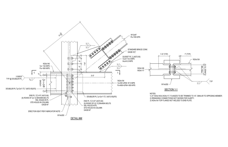
I think you should conclude this thread and consult your IRL peers/management. For clarity's sake, here is a connection design I am working on right now that is very similar to yours. This connection concept is commonly accepted in non-seismic regions in the USA. You will need to adapt the concept to your local code, client preference, and preferred industry practice.

Brace_nbrxon.jpg
 
DrZ is giving you everything you need in this thread.

As noted by others, your original detail looked reasonable. The knee-brace is a bad idea and should be abandoned if not already.

Your original question was about the end plate being too thick and not allowing end rotation. Consider the following:
[ul]
[li]I assume your beam designation 1000x420x40x32 means you have a beam 1000mm deep, 420mm wide, 40mm flange, and 32mm web[/li]
[li]The moment of inertia of this section is 9822x10[sup]6[/sup]mm[sup]4[/sup][/li]
[li]Where the beam connects to the end plate it looks like you have about 860mm of depth engaged. The moment of inertia of the engaged web(860x32) is 1696x10[sup]6[/sup]mm[sup]4[/sup][/li]
[li]The bending stiffness of the engaged web is 17% of the stiffness of the beam section. So without considering flexibility in the end plate, you've already got a connection that is fairly flexible relative to the beam[/li]
[/ul]

Somewhere in this thread you mentioned you're designing the structure as well. If the software you're using allows it, try adding a partial moment release at the end of this member and see what kind of moment it attracts. If you feel it necessary, you can always design for the end moments to be transferred through the web.

Something that I don't think has been mentioned, and I think about often is the connection on the left. With the deep end plate and gusset, that connection is likely much closer to being fixed than pinned.

One last thing, why the PJP on one side of the web and the 8mm fillet on the other? You're indicating 8mm effective throat on the PJP but providing 5.7mm effective throat with the fillet weld. You should keep the weld strength balanced. And for the thickness of the web/end plate and the uncertainty in the end rotation with the thick end plate, I would be using a minimum 10mm fillet.
 
Good morning human909/DrZoidberWoop/CANPRO and all,

Thank you so much for the suggestions and further explanations. it's an awesome forum to get your concerns fixed.

I have raised my concern during my team technical meeting and concluded the thread to team as well. The general agreement is "without knee brace is reasonable solution" same as you noted and i will use this one. for the web welding, it's a typo, i want to use PJP plus fillet weld both side of web , not fillet weld one side and PJP one opposite side.

Thank you all again.

Best regards!
 
Status
Not open for further replies.

Part and Inventory Search

Sponsor