zeroburn315
Aerospace
Hello Everyone,
I am trying to understand this machinery however I am not able to get around it. If anyone can shed some light that will really help me
Link
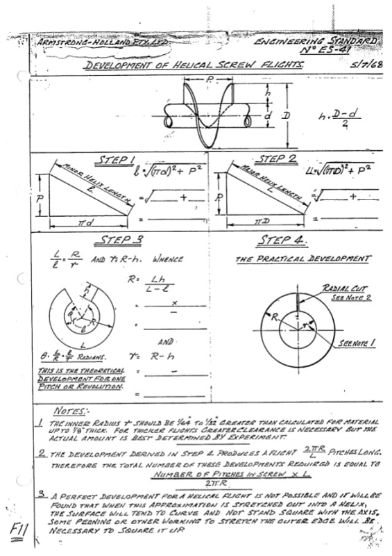
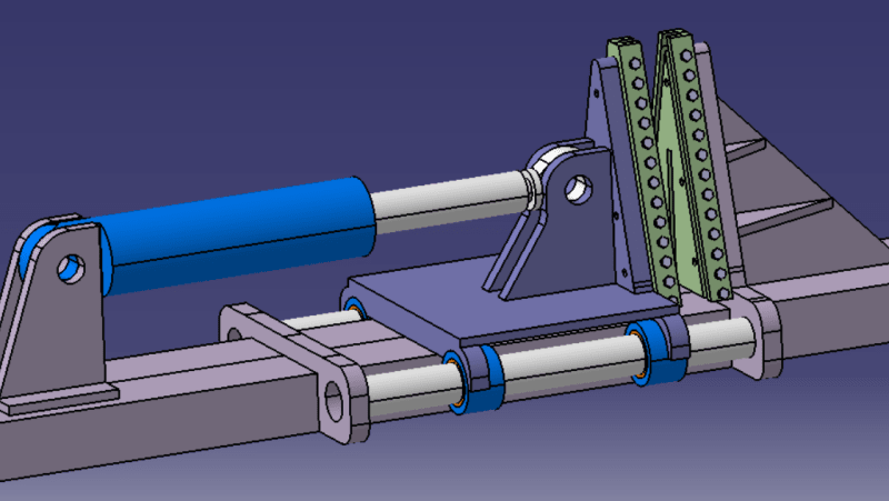
1) Why is the machine Tilted? What should be the tilt angle?
2) Why is the back support very strong? Basically from what I understood, there should be 0 movement in the support
3) Why the Standard flight flat plate calculations does not match the results? I have even used catia and soldworks to flatten the spiral, however there is always a gap after getting desired pitch. i.e. the OD and ID should be less than calculations
4) What should be done for spring back? If I increase the pitch, I dont know how much to increase since that will again change the Inner Dia.
I am trying to making this machine however I am not able to understand its theory. I have done many budget trials however the results are confusing me further. If anyone can shed light at this topic in Detail, that would be really helpful.
This is my concept Drawing (Top Part Only):
I am trying to understand this machinery however I am not able to get around it. If anyone can shed some light that will really help me
Link
1) Why is the machine Tilted? What should be the tilt angle?
2) Why is the back support very strong? Basically from what I understood, there should be 0 movement in the support
3) Why the Standard flight flat plate calculations does not match the results? I have even used catia and soldworks to flatten the spiral, however there is always a gap after getting desired pitch. i.e. the OD and ID should be less than calculations
4) What should be done for spring back? If I increase the pitch, I dont know how much to increase since that will again change the Inner Dia.
I am trying to making this machine however I am not able to understand its theory. I have done many budget trials however the results are confusing me further. If anyone can shed light at this topic in Detail, that would be really helpful.
This is my concept Drawing (Top Part Only):