Continue to Site

Eng-Tips is the largest engineering community on the Internet

Intelligent Work Forums for Engineering Professionals

  • Congratulations GregLocock on being selected by the Eng-Tips community for having the most helpful posts in the forums last week. Way to Go!

Screw Flight Blanks Machine Logic? 1

Status
Not open for further replies.

zeroburn315

Aerospace
Sep 26, 2013
13
Hello Everyone,

I am trying to understand this machinery however I am not able to get around it. If anyone can shed some light that will really help me

Link

1) Why is the machine Tilted? What should be the tilt angle?
2) Why is the back support very strong? Basically from what I understood, there should be 0 movement in the support
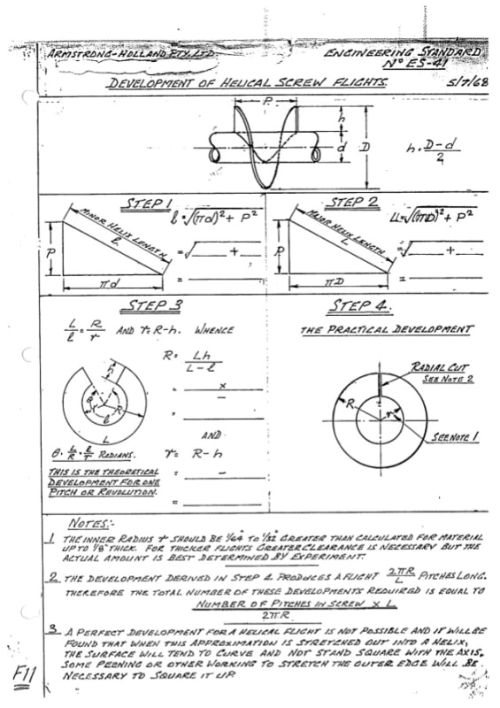
3) Why the Standard flight flat plate calculations does not match the results? I have even used catia and soldworks to flatten the spiral, however there is always a gap after getting desired pitch. i.e. the OD and ID should be less than calculations
4) What should be done for spring back? If I increase the pitch, I dont know how much to increase since that will again change the Inner Dia.

I am trying to making this machine however I am not able to understand its theory. I have done many budget trials however the results are confusing me further. If anyone can shed light at this topic in Detail, that would be really helpful.
This is my concept Drawing (Top Part Only):
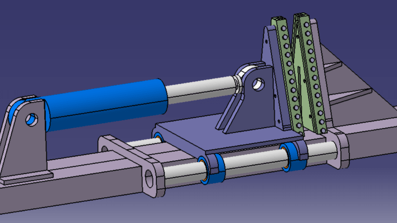
Test_jdkahe.png
 
Replies continue below

Recommended for you

zeroburn315,

Your device looks to me like a hydraulic clamp, designed in 3D[ ]CAD.

[ol 1]
[li]The only tilt I see is the 3D[ ]view. This is extremely easy to do in CAD, and it makes for a clear view.[/li]
[li]A hydraulic ram can deliver hundreds if not thousands of pounds force. Those heavy duty brackets have been sized appropriately. [/li]
[li]I don't see a screw anywhere. Those round things on the bottom on either side look to me like shafts with bearings.[/li]
[li]What is likely to spring back? Are you talking about backlash?[/li]
[/ol]

--
JHG
 
1) Why is the machine Tilted? What should be the tilt angle? To make it easier for the machine operator to manipulate the parts.

2) Why is the back support very strong? Basically from what I understood, there should be 0 movement in the support. Because the machine is capable of producing a lot of force, even if its full capaicty is not needed for the product shown in the YouTube.

3) Why the Standard flight flat plate calculations does not match the results? I have even used catia and soldworks to flatten the spiral, however there is always a gap after getting desired pitch. i.e. the OD and ID should be less than calculations Poisson

4) What should be done for spring back? If I increase the pitch, I dont know how much to increase since that will again change the Inner Dia. Develop a set of empirical data.
 
For flat pattern:
spiral-flight-development-1-638_ybnqt7.jpg


Incremental bending on radial lines to generate the flight.

Ted
 
Thank you for replying to my queries. Can you please also let me know:

3) The person in the video states that there will be no deformation by this method. Therefore very accurate results. I dont understand then why do we need to consider the deformation in the calculations? In other words if there is a deformation then how to account for that in the calculations.
4) The springback cannot be calculated?

@hydtools
I have already done this calculations however the results are same as Catia. which is standard calculations. The Note says that radius has to be greater than calculated however if I decrease the calculated radius, I get more accurate results. For 3rd Point, Noted however what is the solution for that? I believe there is more to this calculations because of the plasticity of the material. I got some values from Russian company who were making this machinery and their values were a little bit less depending on the pitch which were matching exactly on pipe/shaft. I am trying to understand that concept.


I have made the complete machine in Catia now before I start fabricating it, I want to clear this point so there is no regrets later. Again thanks for helping me out, really appreciate it.
 
Having been around these machines some 50 years ago, I may be able to offer a few pointers. The machine is usually inclined at 45-to-50-degree angle to enable 2 things, one to center the blank on guide pins, two to aid the operator in loading and unloading. Remember that because of the difference in pitch angle between the inner and outer faces of the flight the metal has to stretch as the helix is formed. Parametric modeling programs do not deal well with patterns that stretch or shrink hence the problems generating a flat pattern.
Since most of the forming load is at the center of the flight, the design of your machine does not look adequate at the top/ center.
B.E.

You are judged not by what you know, but by what you can do.
 
@berkshire Thank you very much for the reply. Can you please elaborate what you meant by center the blank on guide pins? Isnt it supposed to be resting on both guides anyways even if it is not tilted? Also if it has to be tilted, can you please let me know how to calculate that angle?
Regarding the pitch angle difference, I read a patent on this machine here:

Patent PDF

It clearly says that we have to take the mean radius of the flight for center of bending hence equally formed on inner and outer pitch. Am I interpreting it wrong?
I understand regarding the stretch and parametric modelling, however there are companies who make these machineries, and they have perfected their software to get accurate ID and OD for blanks. I have also used those in demos.

Can you please also elaborate on last part? The Forming load is variable for different sizes of flights thats why I had balance it. Though I am planning to add stiffeners to it and changed the model a bit like this and make only small flights from this die for now, since its not for commercial purpose, its for my own use:

1_tg8fk9.png


Looking forward to your reply.
 
zeroburn315 (Aerospace)(OP),
The dies that I was involved in would form the flight in one or two blows max, they looked more like the yellow part of your model. The guide pins I was referring to positioned the flat blank for the initial blow. The operator would position the blank, stroke the machine once, rotate the blank a few degrees then hit it again to finish up. the press was a Danly OBI mechanical punch press.
B.E.

You are judged not by what you know, but by what you can do.
 
Hello everyone,

I have a simple hydraulic press and I want to convert it to a bending machine for the helixes of the Archimedes screws (varieties of pitch) and I need your help to have the mold manufacturing method (angle of inclinison, length ).
Thank you very much.
Mold_auger_flight_mksmjz.png
Capture_d_%C3%A9cran_2022-04-17_132859_n7raof.png
 
Status
Not open for further replies.

Part and Inventory Search

Sponsor