Eng-Tips is the largest engineering community on the Internet

Intelligent Work Forums for Engineering Professionals

Screw holes in flat head flange 1

Status
Not open for further replies.

Serpent_Timber

Mechanical
Jul 10, 2024
3
0
0
US
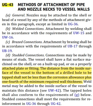
I’ve got a flat head flange that I did the calcs on following UG-34. It’s got a through hole in the middle which follows UG-36 requirements for size to not need support. This flange will have a junction box attached on the dry side of it to support cabling. As such, there are some tapped screw holes on the flange. They do not go through the entire flange thickness. I don’t see this called out in the BPVC so am unsure how to incorporate them into calcs.

This flange has passed hydrostatic testing already and they’ve had a previous flange very similar where the analysis simply stated “not subject to loading”. Team is having disagreements on if this is sufficient and if we can justify it by referencing the BPVC somewhere.
 
Replies continue below

Recommended for you

Nothing in Appendix 2 addresses holes drilled into the flange. In fact the bolt holes themselves don't even factor into the Appendix 2 flange analysis, so if the tapped screw holes are smaller in diameter than the flange bolt holes you can probably make a case for ignoring them.


-Christine
 
OP,
UG-34 requires a minimum head thickness. If the tapped holes create a thickness less than the minimum, then I do not think that would be allowed. As a general rule, I would consider drill and tapping the outside of a pressure retaining structure, a no-go. Is there a reason why welded studs can't be used to support the junction box?
Also, I do not think this is correct statement in terms of a pressure vessel being subjected to internal pressures but external pressures as well. One could argue that the outside of a vessel is as much a part of the pressure retaining surface as the inside.
I hope I am reading your question correctly, as noted a sketch would be helpful.
 
445FE75A-F5DA-4DB7-BE57-40C8BA5F0D2A_spf3ht.jpg
CB68CCF2-AEFF-4156-A437-BD5A91547D0E_x5bxgm.jpg


Very similar to this setup. Has a through hole in the middle of the flange and a few blind holes around the through hole. I’m looking into UG-36(a)(2) now as it could possibly apply here and this flange is hydrostatically tested and passed.
 

Wouldn’t that mean you’d never be able to have an opening in a flange? Quite common to have through holes for connectors and cabling on these flanges. I did question that statement on the other report too, but alas that engineer is no longer working here. Not sure about welded studs, I’d have to ask around on that one.
 
OP,
No, these are prescribed openings. In terms of a pipe being screwed in, the pressure retaining surface transfers to the pipe walls as far as a grommeted cable gland, the cable gland itself becomes the pressure retaining surface. The issue I am pointing out, is you are reducing the thickness in a certain location and relying in that thickness to retain the vessel pressure without any accounting for it. You could argue the bolt itself becomes part of the system, but I don't know if that is a true statement. The pictures in the example you provided could indicate the validation of the usage you describe but they do indicate a dimensional quantity thickness, which if engineered, I would assume has been checked. I would at least dimension the thickness remaining and run a check against the MAWP and see if it passes muster. Just my thought process, you have 1/8" material remaining after drilling and tapping, the vessel has corrosion allowance of 3/16" = leak.
 
OP said:
As such, there are some tapped screw holes on the flange.

Devil's in the details. How big are these screw holes? How deep? If they are "few & small" and you can meet UG-43 depth requirements I'd not worry about it.

Regards

Mike

The problem with sloppy work is that the supply FAR EXCEEDS the demand
 
If you calculate the opening as a diameter that includes the tapped holes you will be fine, then use UG-43(d) and (g) for the tapped hole depth (as others have said).
 
OP,
Look at the following scenario:
1. The flange in the pic is a pressure containing part.
2. There is a through-hole at the center of this flange.
3. There must be a connecting part (not in the pic) which is connected to the flange though 4 screws.
Now here is what will happen:
4. The connected part will have to be pressure part (as it will fall at the pressure boundary).
5. Did you do the bolt/screw sizing for the four screws to take the pressure and gasket seating load?

Draw up another picture and show what is connected through the screws or members to understand clearly where the pressure boundary ends.

With info you provided, the connected part has to be designed as a pressure part.

GDD
Canada
 
Too bad that people still do not understand the purpose of Div. 1 Appendix 2. Appendix 2 is only for custom design flanges other than B16.5. B 16.47. Don't ever test standard flange by Appendix 2.
As for the center hole on blind, check B16.5 or B16.47, it states that under certain hole size, reinforcement is not required. Bigger than that, just perform reinforcement analysis. I saw the calc from vessel vendor many times, nothing new.
For the tiny screw hole, your bolting can be considered as part of the flange as they are completely engaged, not an issue. Threaded connection which has no different to screw hole are not uncommon in pressure vessels, and due to small size, it is exempt from reinforcement analysis.

For the external loads, yes many times we will say external load does exist, but negligible. Not even bother to run any stress analysis. This is engineering judgement. We have hundreds of thousands of instrument nozzles, 1.5", 2" and 3", with all kinds of instruments attached to it. And the industrial common practice (I am in Houston energy corridor with many oil companies and engineering firms here)is to ignore its impact so no WRC 107 analysis needed nor re-checking flange rating . Only "process nozzles" need WRC107 analysis and check flange rating per UG-44(b) or equivalent pressure method.
In all, if you have center hole, just if reinforcement is needed, ignore the tiny screw holes, and for the light external weight on blind, also ignore it.
Code also allow if you are duplicate something from the past which has been successfully operated, no need to do any analysis.

Flanges were invented without detail stress analysis before Appendix 2 exists, as simple as that. Let me know if I am wrong.
 
jt1234,
You are 100% correct and I agree with your thoughts on whether stress analysis and reinforcement analysis are required.
We will need OP to comment further but I do not think those pictures and drawings are what is being discussed in OP's original post.

OP posted the pictures and drawing to show that blind and through holes are common on flanges, to which I agree. OP's flat head flange is using UG-34, which I think would be appropriate based on the description. OP's original question, as I read it, indicated there were blind holes of unknown depth, machined into the external surface of the head flange and where in the BPVC, are holes such as these, discussed, in terms of performing any sort of check.

In the absence of drawings or specific dimensions, it is difficult to determine whether a 1/4" deep 6-32 hole in a 2" thick flange or a 7/8" deep 1/4-20 in a 1" flange are being considered. Without that information it is difficult to speak in any sort of specific terms about what should and shouldn't be checked.

I would not think any sort of stress or reinforcement considerations would be needed since it is for attaching a junction box and the term "not subject to loading" in this sense would be appropriate, but I would not think that the remaining thickness of material, being unknown, can go unaccounted for, in terms of pressure retainment. I would not think hydro would be the appropriate method in determining if the remaining thickness is sufficient. UG-43 does provide a method for determining if the remaining thickness is sufficient. Appendix 30 could also be considered but for studded connections, it too refers back to UG-43. That said, I may have read OP's original post incorrectly and this indeed should be Appendix 2 and in such a case I refer back to jt1234
 
OP,
There is lots of confusion. You are releasing the info bit by bit.
Can you send a hook-up dwg. with the connected parts?

GDD
Canada
 
I insist with my post 11Jul24 12:05
Any sketch?
With dimensions included, otherwise it's not a sketch.
More details - better answers (by Little inch)
Regards
 
Status
Not open for further replies.
Back
Top