Eng-Tips is the largest engineering community on the Internet

Intelligent Work Forums for Engineering Professionals

Seeking Advice on Discharge Pump Flange Loads and Pressure Thrust in Slurry Pump System

Status
Not open for further replies.

Jharvey2525

Mechanical
Jul 18, 2019
14
0
1
CA
I have a rubber hose installed on the discharge of a pump, but its stiffness and flexibility characteristics are unknown. The client prefers these hoses for their wear resistance and ability to reduce both vibration-induced wear on the pump and loads on the nozzles. While these hoses are relatively rigid, they can elongate slightly under pressure.

Given this, I included pressure thrust in my AutoPIPE analysis. Although the pipe stress itself isn't a concern, the load on the discharge pump flange exceeds the allowable limit by about 30%. During operation (60 psig & 95°F), there seems to be pipe lift-off at the top hanger (see attached image), and this additional load appears to be transferring to the pump nozzle.

After discussing with a colleague, he suggested I might be overestimating the impact of pressure thrust. He believes it would be negligible on the pump discharge as most of the thrust would be absorbed by the pump internals. My main concern is the extra piping weight on the pump discharge due to the support lift-off, though I’m questioning if I’m approaching this correctly.

Initially, I considered a spring hanger to mitigate the load during lift-off, but my colleague thinks it's unnecessary. I'm seeking the simplest solution to address this issue without adding a spring hanger, if possible. Please assume the pipe routing will remain the same.

Thank you for your insights.
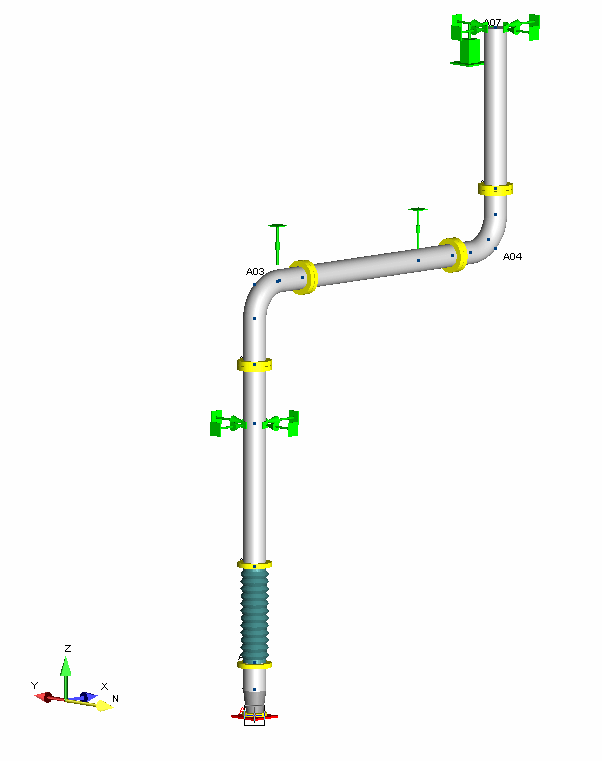
Screenshot_2024-08-20_115338_qaiy7t.png
 
Replies continue below

Recommended for you

I think I see what is going on now. The pressure thrust is applied in both directions at the hose/expansion joint by the program when you choose to activate pressure thrust. Therefore you have the 9900# applied in both directions by the program. I was thinking that it was only applied manually up by you.

If the hose or expansion joint were perfectly flexible then there would be 9900# acting on the anchor/pump nozzle and a separate 9900# acting on the 1st elbow at the top of the discharge. The anchor at the pump will resist this force and 9900# will show up at the anchor report output. At the other end at the elbow the 9900# will cause the hose to expand until the sum of the forces due to the weight of the pipe of the discharge line plus the force due to bending by deflection of the horizontal run between the 1st and 2nd hangers bending like a guided cantilever equals the 9900# applied thrust to balance it otherwise the pipe will blow apart. No telling how much the hose or expansion joint would stretch if it were perfectly flexible and provided no resistance force itself to the thrust force. In this case no matter how much the hose stretches there would be no opposing force on the anchor due to the stretching of the hose so the net force on the anchor would always be the full pressure thrust if the hose was absolutely flexible since no matter how much you stretched it the resulting force of delta L times spring constant will always be zero since the value input for the spring constant would be zero for a perfectly flexible hose.

On the other hand if the hose were perfectly rigid then the 9900# on the anchor will be balance by the 9900# applied in the opposite direction to the elbow since any stretching whatsoever of the hose will produce a force to counterbalance the 9900# forces applied in the opposite directions. Then there would be zero load on the anchor and zero load on the elbow because the 9900# load balances itself.

Therefore in-between a perfectly flexible and perfectly rigid hose the load on the anchor will be somewhere between 0 and 9900#. In your case the load is 7241#. The stretching of the hose is 0.068 inches per your output for Dz at the 1st hanger. 0.068 x 40000 is the opposing force due to stretching of the hose or 2720#. 9900# - 2720 = 7180# which is the approximate force on your anchor/nozzle.

This indicates that the upward 9900# trust is being balanced by the weight of the pipe above, the bending of the horizontal run like a guided cantilever beam, and the opposing force due to the stretching of the hose.
 
Hi Everyone,

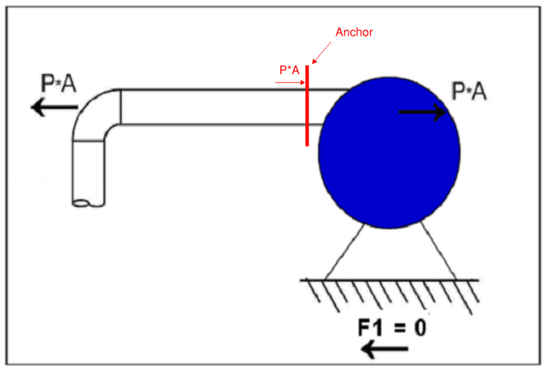
Thank you all for your helpful input. I’ve concluded that I incorrectly included pressure thrust in my analysis. By anchoring the discharge flange of the pump, the software appears to calculate the total P*A pressure on the anchor, when most of this force is actually transferred to the pump and its base (see attached image). The difference in the indicated load versus the total pressure thrust load is likely due to the flexibility of the pump nozzle and the stiffness of the hose.

Screenshot_2024-08-23_145905_dj9jr1.png


As many of you have pointed out, the likely load on the pump discharge flange due to hose elongation will be an upward force, not a downward one, and well within the allowable limits. Excluding pressure thrust from the nozzle load analysis should result in acceptable flange loads.

Apologies for the delay in reaching this conclusion. If you find any issues with my reasoning above, please let me know.
 
"By anchoring the discharge flange of the pump, the software appears to calculate the total P*A pressure on the anchor, when most of this force is actually transferred to the pump and its base."

By anchoring the discharge flange of the pump, the software places the total P*A pressure on the anchor.

Yes, that's takes the load off the pump.

When you do not anchor the flange, this force has no alternative but to be resisted by the pump and its base. Pressure thrusts (end cap forces) are always transmitted by the containing pipe by its axial tension. The fluid inside cannot cause or transmit tension. Only the pipe can do it. Axial tension in the pipe will be transferred to the pump flange, its bolts, the nozzle and pump casing, then to pump anchor bolts.

Thrust never goes into the pump internals. The pump impeller is generating pressure from its exit velocity converted to pressure, which generates both pressure and thrust (end cap force/pipe wall area) in the pipe, which are resisted by the pipe wall's ring/hoop stress, which x Poissin ratio = axial pressure stress + the "End cap forces/pipe wall area" which together make up the total axial tension stress in the pipe wall. Dead load and thermal component stresses are superimposed on those pressure stresses to arrive at the net total axial stress, which can be compressive, if the those component stresses are greater than the sum of all pressure tension loads. The pump provides the opposing thrust (end cap force) by virtue of the discharge pressure it provides at the pipe inlet.

--Einstein gave the same test to students every year. When asked why he would do something like that, "Because the answers had changed."
 
Momentum forces are also present at bends, because fluid flow (mass x velocity) is changing direction by 90°. That will add to the pipe wall stresses if the joints are welded, or clamped, or fused, or glued in place, in addition to the above.

If the pipe joints are push-in type, then the momentum forces must be resisted by bend anchors, often seen on concrete push-in joint type piping as large masses of concrete holding the bends in place against the soil.

--Einstein gave the same test to students every year. When asked why he would do something like that, "Because the answers had changed."
 
1503-44 thank you for the additional information, this topic and issue is becoming a lot more clear to me now.

Snickster, I only just saw your latest post well after I made my last post. But I believe you summarized what is going on perfectly, certainly better than I did.

To summarize, while this pressure thrust force will cause the hose to elongate and the piping to lift off the support, the force indicated on the anchor from the software is overstated as withstanding all of the thrust load when in actuality this won’t be the case.

A potentially more accurate way to simulate the pump flange loads may be as sentrifice indicated by removing the pressure thrust and putting a force on the first elbow equal to the thrust load (9900#). Does this make sense?
 
To summarize, while this pressure thrust force will cause the hose to elongate and the piping to lift off the support, the force indicated on the anchor from the software is overstated as withstanding all of the thrust load when in actuality this won’t be the case.

I believe the forces calculated by the program are correct for the spring constant you use of 40000. The more flexible the hose the more force will show up on the anchor/pump nozzle. For expansion joints at pumps, tie-rods are always used to take the pressure thrust. I never installed an expansion joint without tie-rod at pump but in oil and gas, refining, chemical plants process piping, expansion joints are rarely used. The piping is routed flexible even if it has to be ziz-zagged at the pump to get it flexible. Clients do not like expansion joints in those industries. Using a hose connection is an odd situation and would only be done in slurry type non-hazardous situations like you have. However I believe the thrust loads shown in your program are correct for how you modeled it. I would discuss with the pump manufacturer to see how they considered this thrust load in the design of the pump, if at all. I would not assume that the pump can handle the thrust load. The thrust load will be on the volute acting down as this is where the pressure in the pump is located. It could cause moments and defection as this load is transferred through the bowl to the pump foundation.

A potentially more accurate way to simulate the pump flange loads may be as sentrifice indicated by removing the pressure thrust and putting a force on the first elbow equal to the thrust load (9900#). Does this make sense?

No unless you get word from the manufacturer that the thrust load on the pump has been included in the design of the pump.
 
Flexible hoses are not expansion joints. Expansion joints have convoluted walls to allow axial movement, and they require tie rods. Flexible hoses have braided or similar reinforcement and can be designed to contract axially due to radial expansion with an increase in pressure. That is why I said earlier that the hose should be bent 90 degrees. The bend allows the hose to flex to accommodate any deflections. Look at the catalogs or design manuals for flexible hose.
 
OP,
What is the pump manufacturing Standard? There will be also 'Moment' (bending/torsion etc) component from the loads that should satisfy the pump flange allowable loads. The best away to do it is through a Free Body Diagram (FBD).

Loads on the pump nozzle will come from sustained and thermal loads.

How are you qualifying your computational result with Manufacturer given Flange Allowable? Does the program has it inbuilt for the pump standard?

Because you already have the pump, the reaction forces from the piping/hoses must satisfy the pump flange allowable loads.

GDD
Canada
 
OP,
Did you try the following:
1. Remove the hanger (that lifts off) from the elbow. We need the elbow to be free to flex.
2. Reposition the second hanger on the mid-span of the horizontal span(depending on the span length), otherwise move the first hanger away from the elbow keeping the second hanger in place.
3. Support the vertical pipe at the top as practicable as possible. Put a Riser Clamp and support it by a spring hanger. This should take the weight of the vertical run from the discharge.
Providing support at the bottom tend to cause column buckling loading in vertical pipe.

4. Not sure what type of support you put on the vertical run. You can move this to the bottom as a guide support to keep the hose aligned to the pump discharge nozzle.

GDD
Canada
 
Hi GD2,

Thank you for your response. Regarding your questions:

[ul] [li]The pump is a Warman STAH 14/12, which adheres to Hydraulic Institute 6, ISO 14001, OHSAS 18001, and is CE certified.[/li] [li]The moments indicated on the anchor are negligible compared to the allowable moment loads provided by the pump manufacturer.
Screenshot_2024-09-04_111058_psezqm.png
[/li] [li]I was directly comparing the loads from the software to the allowable loads from the pump manufacturer. Is this what you were asking?[/li] [li]Yes, I agree that the piping support arrangement should work with the allowable equipment loads and not the other way around whenever possible.[/li] [li]The hangers are positioned as close to the mid-span as possible given the nearby structural support members.[/li] [li]The existing support on the vertical run is currently just a guide to keep the hose aligned to the pump discharge, using the nearest structural members to accommodate the current location.[/li] [/ul]

From previous responses, I gathered that the pressure thrust is not fully acting at the pump flange-to-piping connection, as I had set up in the software. The software output shows the full endcap force on the anchor (pump flange), but in reality, this force would act on the first elbow in the vertical run and on the pump casing opposite the nozzle, as indicated in the photo. A small portion of the thrust would come from the discharge reducer, and the piping should be under tension from the upward thrust force. I hope this is the correct line of thinking now.
 
OP,
Thank you for sending the pump details. Did you attach the F[sub]x[/sub] and M[sub]x[/sub] table for the current pump? I thought you had problem with the discharge nozzle. If it is, you need to relieve the gravity/weight load of the vertical discharge hose with a riser clamp and two spring hangers (as this is somewhat a hot service). If you need to provide support steel, you need to.
This is a simple piping arrangement.


GDD
Canada
 
GD2,

That is the flange load table for the new pump (Warman 14/12 STAH) that I sent. Yup you are correct, my issue was with the discharge flange loads (vertical). This wasn't necessarily due to the weight/load of the piping however, but likely an error in how I was modelling & analyzing the pressure thrust in the line. Agreed, this is a simple piping arrangement, but it has proven a bit challenging to me for a few different reasons. The area is also a bit of a rats nest of piping, and support locations are tricky to MacGyver with all of the obstacles.
 
OP,
Check your work. F[sub]Z[/sub] will be the gravity load and its compressive. With other drawings you have provided, the pressure thrust will be in another axis.

Your second drawing with P*A marking layout don't seem to match your first AutoPipe model. I may be wrong but I can't figure it out without the x-y-z coordinates.


GDD
Canada
 
Jharvey2525 said:
By anchoring the discharge flange of the pump, the software appears to calculate the total P*A pressure on the anchor, when most of this force is actually transferred to the pump and its base (see attached image).
Yes, but assuming a rigid pump as you have by using an anchor to represent the nozzle, forces applied to a nozzle are the same thing in terms of nozzle load limits to forces transmitted through a nozzle. There is only a difference when the nozzle flexibility is included. Where the forces are ultimately resisted doesn't absolve you of keeping forces and moments applied to the equipment via the nozzles within the vendor stated limits.

Jharvey2525 said:
the likely load on the pump discharge flange due to hose elongation will be an upward force, not a downward one
Uh, disagree. Pressure thrust acts on both ends of expansion joint, equal and opposite forces and all that.

Compositepro said:
Flexible hoses are not expansion joints. Expansion joints have convoluted walls to allow axial movement, and they require tie rods. Flexible hoses have braided or similar reinforcement
This is an important point. You are modeling essentially an unrestrained bellows joint, if there is reinforcement in the hose to resist length changes then the pressure thrust the program gives you may be artificially high.

 
Status
Not open for further replies.
Back
Top