Eng-Tips is the largest engineering community on the Internet

Intelligent Work Forums for Engineering Professionals

Seeking Advice on Discharge Pump Flange Loads and Pressure Thrust in Slurry Pump System

Status
Not open for further replies.

Jharvey2525

Mechanical
Jul 18, 2019
14
0
1
CA
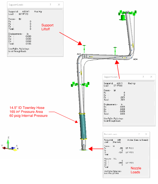
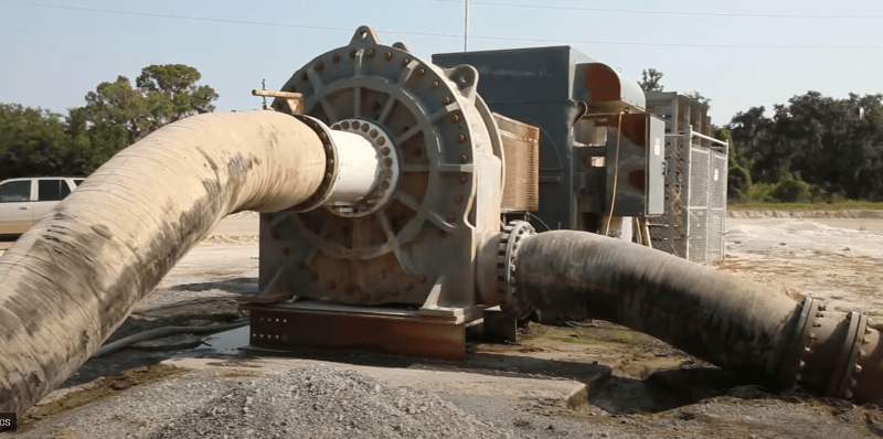
I have a rubber hose installed on the discharge of a pump, but its stiffness and flexibility characteristics are unknown. The client prefers these hoses for their wear resistance and ability to reduce both vibration-induced wear on the pump and loads on the nozzles. While these hoses are relatively rigid, they can elongate slightly under pressure.

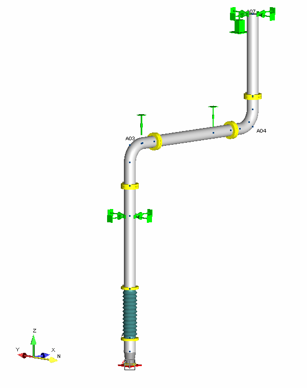
Given this, I included pressure thrust in my AutoPIPE analysis. Although the pipe stress itself isn't a concern, the load on the discharge pump flange exceeds the allowable limit by about 30%. During operation (60 psig & 95°F), there seems to be pipe lift-off at the top hanger (see attached image), and this additional load appears to be transferring to the pump nozzle.

After discussing with a colleague, he suggested I might be overestimating the impact of pressure thrust. He believes it would be negligible on the pump discharge as most of the thrust would be absorbed by the pump internals. My main concern is the extra piping weight on the pump discharge due to the support lift-off, though I’m questioning if I’m approaching this correctly.

Initially, I considered a spring hanger to mitigate the load during lift-off, but my colleague thinks it's unnecessary. I'm seeking the simplest solution to address this issue without adding a spring hanger, if possible. Please assume the pipe routing will remain the same.

Thank you for your insights.

Screenshot_2024-08-20_115338_qaiy7t.png
 
Replies continue below

Recommended for you

Thrust always come in equal and opposite flavors.

Looks like another case of very small thermal movement causing large forces? That's mostly a theoretical problem, as after 0.01" of movement, force becomes 0 and further movement stops. If that's the case, let it slide that 0.01".

Downward pipe weight would have to be transmitted to the pipe through the flex coupling. Is that really possible? You say the pipe is lifting off at the potential spring hanger, but probably not that much movement at 95°F.

Why are the two rod supports not taking vertical loads? Is one force up and the other down? Maybe use just one above the pump. That should be made to carry the bulk of the pipe weight.

If there is still too much of a net down force at the pump, try putting an anchor on the flange and hanging the pump from that. Or a vertical support/or anchor at the first yellow flange.
Your pipe force will be captured by the flange anchor.


--Einstein gave the same test to students every year. When asked why he would do something like that, "Because the answers had changed."
 
Hello 1503-44,

The movement from the analysis is a little more than 0.125" (1/8"), which according to Autopipe then provides no support at the first hanger on the elbow. Maybe this is conservative as I'm unsure of the stiffness of these hoses. The second hanger support is still active and supporting load. Some additional info is that the elbows are basalt lined, so they are very heavy (~1800 lbs). Is it safe to assume that this movement is little enough that the inherent flexibility in the system is enough to bring the loads on the pump discharge below allowable? Can this be quantified?

I agree in practice that the above mentioned setup should work without over loading the pump discharge nozzle. In theory I'm just having trouble wrapping my head around this, but if the hose elongates from the pressure thrust and causes liftoff at the first hanger, where is all of the additional piping weight being transferred to?

My experience with using these rubber hoses are limited so insight into how these fittings fit into the piping design in terms of their elongation, pressure thrust, and support design is greatly appreciated.
 
It's probably trying to go to support #2, if not the pump, or both.

I think your best bet is to support right at the pump flange, or at the first yellow flange below the hose, or at the 2nd above it, if the hose is too flexible to actually transmit the weight to the pump flange. If your load is thermal, piping flexibility helps reduce that. If it's mostly weight there, you need immediate support. Not much other choice. As it is, w/o springs, upward growth is free to move, so no thermal load is created anywhere, but then that just dumps all weight back on the pump flange.


--Einstein gave the same test to students every year. When asked why he would do something like that, "Because the answers had changed."
 
After discussing with a colleague, he suggested I might be overestimating the impact of pressure thrust. He believes it would be negligible on the pump discharge as most of the thrust would be absorbed by the pump internals.

I believe it depends on the type of pump and how the bowl is supported. For instance, with a centrifugal pump with foot supports directly under the bowl and discharge centered on bowl, the pressure thrust would be transferred to the supports through the bowl to the supports without much moment loading and deflection I believe. However, with overhanging pumps and discharge nozzles not centered on the bowl there will be high moments developed due to pressure thrust eccentric to the pump supports that would need to be considered.


My main concern is the extra piping weight on the pump discharge due to the support lift-off, though I’m questioning if I’m approaching this correctly.

I am not sure how lift off is occurring. Have you modeled the hose with a high spring constant? It seems like any thermal expansion of the vertical discharge line would be taken up by compression of the hose as it cannot be that stiff that it will support the pipe to push it up under thermal expansion to cause it to lift off of the first support.

It could be lifting up due to rotation of the horizontal run about the second hanger. If so then this would not put load on the pump due to pipe being supported by the pump nozzle when lift off occurs. It would create an upward force on the nozzle though based on the stiffness of the hose you modeled, but again the stiffness of the hose should be very small.

Lift off can also occur by pressure thrust on the upper elbow if you modeled pressure thrust there, but if this occurred the pressure thrust itself would be pushing the pipe up and supporting the pipe so no loads should be transferred to the pump except that developed by the hose in tension which should be negligible with low stiffness of hose.

I think you may have something wrong with the way you modeled it in Autopipe.
 
Hello Snickster,

Thank you for your response.

Just to clarify, it is a centrifugal pump. The lift-off doesn’t appear to be caused by thermal expansion or rotation around the second hanger. However, as per your third point, I have modeled pressure thrust on the rubber hose in AutoPIPE, and this is what is causing the hose elongation and resulting in the lift-off from the first hanger.

If I understand correctly, you're suggesting that the piping weight is being self-supported by the pressure thrust. Is that accurate? If this is true, is any of this thrust force being transferred to the pump discharge flange, or is the loading I'm seeing in AutoPIPE potentially overstated due to standard "blanket" calculations using "dumb" software? How can I accurately assess if the pump flange loadings are acceptable in this situation?

Sorry for the barrage of questions as I try to wrap my head around this issue.
 
If lift off is caused by pressure thrust and the hose elongates, then there must be tension in the hose equal to the hose spring constant time the deflection of the hose. This should be very small for 1/8" deflection of the hose. So this would have be an upward force. I don't see where any vertical down forces on the pump nozzle are coming from.

What are the force and moments on the pump nozzle? What is the pressure thrust? What is the pipe diameter?
 
What is the value of Fz at the pump nozzle? I cannot read it.

What did you model the stiffness of the hose to be laterally and axially?

In the model shown above what is the single black line versus the full pipe line depiction. Is the single line the undeflected shape and the full pipe the deflected shape?
 
Thrust uplift on the left elbow may be countered by opposite thrust at the right elbow. The hose does not appear to be taking any tension load, so there may be a large bending moment in the horizontal.

--Einstein gave the same test to students every year. When asked why he would do something like that, "Because the answers had changed."
 
Apologies for the poor quality image. The Fz is 7241 lbs down, the lateral loads are rather insignificant on the pump nozzle at 258 lbs.

I've played with a few different stiffness but the numbers I'm currently using are 40,000 lb/in axial stiffness and 20,000 lb/in lateral stiffness.

You are correct the black line indicates the un-deflected shape while the pipe shows the deflected shape.
 
There is usually a support pretty close to a pump flange that will take a lot of load coming from the piping system for this very reason. Most of us do not use hoses and expansion joints, unless ABSOLUTELY NECESSARY.

Where they can be advantageous is when they can deflect to absorb movement of the pipe that would otherwise cause load, if the pipe was restrained. Such as from thermal movement. Restraining thermal movement causes thermal load. If it is free to move, no load. In the case where there is just heavy pipe, if the hose does have an axial spring constant, they just move more to resist the same heavy pipe load.

--Einstein gave the same test to students every year. When asked why he would do something like that, "Because the answers had changed."
 
Agreed, we generally avoid using hoses or expansion joints unless necessary. However, the client prefers Townley hoses to reduce pump vibration and flange loads. Here’s an example of the hoses:

Screenshot_2024-08-22_133354_h280ir.png


Assuming we set aside thermal loads and focus on pipe weight vs. pressure thrust, how do these interact? Is it as Snickster mentioned, where pressure thrust supports the pipe, with little to no load on the pump flange?

Snickster:
"Lift off can occur by pressure thrust on the upper elbow, but the pressure would push the pipe up, supporting it, with negligible loads on the pump due to the low stiffness of the hose."

Alternatively, does the entire piping load (with lift-off) transfer to the pump flange via the hose?

In either case, how can I accurately assess the actual loads on the pump flange? Is there a better way to model this or another calculation method?

Thanks again for all the input.
 
I am taking a look at it now with the information you gave me. I am beginning to think that the load on the pump nozzle is due to thermal expansion. You do have 203 F piping and that vertical discharge pipe looks to be about 20 - 25 feet long so there is about 0.3" of thermal expansion there that appears to be causing lift off of the first hanger as well as compression of the hose.
 
I have analyzed this same model where I have removed the pressure thrust from the analysis and in doing so it removes the majority of the loading from the pump flange and causes it too be within the allowable (~2500 lb). In this same simulation, the hanger support located on the elbow is engaged and taking load, so this is why I believe that the thermals are not part of the issue, but it is the pressure thrust causing the problems in some capacity.
 
I have attached my thoughts on the attached PDF. It is difficult to get a definite answer without all the data and model input/output reports and making a lot of assumptions but I tried as best as I could.

In summary I believe the hose is designed to transfer the pressure thrust so that really it does not need to be considered in the calculation. The hose stretches alot more than an equivalent length of pipe which is causing the 1st hanger to lift but the pressure thrust is still being transferred through the hose and being balanced by the opposite thrust force on the pump. Therefore, the net force on the pump nozzle is as you indicated you calculated to be of 2500# with thermal and no pressure thrust I believe. An additional vertical support just above the hose will take this load rather than the pump nozzle and would be better for constructability.
 
 https://files.engineering.com/getfile.aspx?folder=3ad0dbc3-0872-430e-b99f-b9da8bbafeb7&file=Eng_Tips-Pump_Load.pdf
Snickster, thank you for your thorough analysis, I'm impressed. Your time and effort are greatly appreciated. I agree with your assessment that the hose can withstand the pressure thrust and doesn't likely need to be factored into this analysis. You're correct that adding a support to the bottom flange of the hose significantly reduces the load on the pump discharge.

However, it would be ideal to avoid designing an additional support for the discharge, as the foundations are already finalized. If it's necessary, we’ll proceed, but I’d prefer to avoid it if the pump discharge isn’t overloaded.

Regarding the force directionality in the software, it’s undoubtedly showing a downward force on the pump anchor, which I’d like to better understand. It seems the software might be calculating pressure thrust as acting in equal and opposite directions, pulling the hose apart—resulting in an upward force lifting the pipe and a downward force on the pump flange.

However, this isn't really clear to me still.
 
It seems like the pressure thrust should not applied to the anchor that represents the pump nozzle.

In reality, the pressure thrust would be applied in the pump casing and not at the nozzle. As in the pump manufacturer would have already accounted for any pressure thrust in the housing and it would be "double-dipping" to apply pressure thrust at the nozzle.

To fix this, I would consider modeling it as having no pressure thrust at the expansion joint (pressure area = 0) and then apply a standalone force at the elbow (A03) in +Z direction that is equal to the calculated pressure thrust.


As an aside, I would really look at the hose stiffness numbers to be sure they are realistic, they would likely have a big impact and there doesn't seem to be consensus on what they should be.
 
Status
Not open for further replies.
Back
Top