Eng-Tips is the largest engineering community on the Internet

Intelligent Work Forums for Engineering Professionals

  • Congratulations waross on being selected by the Eng-Tips community for having the most helpful posts in the forums last week. Way to Go!

Seismic Behaviour of Truss Frames 1

Status
Not open for further replies.

MburakY

Structural
Feb 8, 2015
12
TR
Greetings,

I was wondering what would be the correct seismic classification for the attached frame. It feels like this is an obvious "moment frame". Lateral resistance is provided by the moment capacity at the column beam connection location.

On the other hand, everything is nearly purely axial. Every action translates into axial compression & tension. And this confuses me if we think about seismic systems and ductilty. Imagine I have to pick a high ductile system. Should this frame be "special moment frame"? I have serious doubts because in order for R to be 8, we should have serious plastic deformation capacity at the "beam" and moderate plastic deformation capacity at the panel zone under cyclic loadings. I am not sure if we can achieve this with axial deformation of the members. Also, High ductile moment frames have very compact beam flanges. How should we project this requirement to truss frames, I dont really know.

I am not aware if codes directly adress this type of frames but they are not rare for the industrial facilities. And sometimes, due to cranes etc, roof load can be high resulting to prevent us from usign R=3 systems. I wonder what would be the opinion of the forum.
 
 https://files.engineering.com/getfile.aspx?folder=2c2d6236-3847-4fc4-adc8-0b506669f010&file=truss.png
Replies continue below

Recommended for you

The characteristic of moment is a couple in rotation, and the member deflects. Does the bend members in the truss frame behave as thus?
 
retired 13,

That's the behaviour in essence in my opinion. Only thing is, a normal beam, as you described "bends" due to moment created by couple forces in flanges. Flanges strech and compressed under the couple. This is the same here. Ideally, truss is a large beam, flanges are the top and bottom chords which stretch and compressed under couple forces created by the bending in the overall frame. Overall frame deflects as such.
I know this is not exactly "moment frame" but I am not sure what it is either in terms of seismic classification.
 
IMO, you shall stick to "truss" classification as explained/discussed below.

I think, under lateral load, the deformation in a typical moment frame would require more energy than the truss frame to produce the same, in another word, the truss frame is much more flexible than a comparable moment frame. Let's put it to a test, apply an unit lateral load on the truss frame, and on a moment frame, and compare the results of deformations (joint rotation and displacements).

I suggest, the moment frame shall be constructed to have a beam-column joint having the same moment capacity as the bent of the truss frame, and the same height and bay width as the truss model. So, what you think, and what are the results?
 

Pls look ASCE 7-16 Table 12.2-1 Design Coefficients and Factors for Seismic Force-Resisting Systems;

C. MOMENT-RESISTING FRAME SYSTEMS;

Steel special truss moment frames; R=7 Ω0=3

What is the reason for selection SMRF? IMRF or OMF could be more economical and simpler.

The structure shall be checked for deflection and redundancy..

I feel the structure is less redundant..

 
HTURKAK,

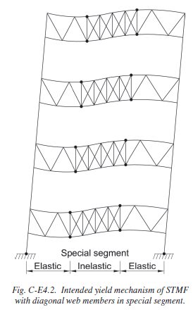
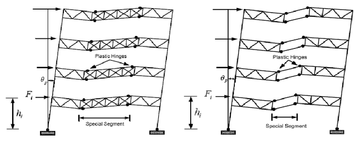
I have considered the special truss moment frame before, but I doubt this fell into the same category. They usually have a special segment, which operates similar to link members of eccentrically braced frames. Please see attached example taken from appendix of seismic provision 2016. Also I have looked up other examples of this system from google, all similar results.

Capture_bvnb60.png

Capture2_ysfqh2.png


Thank you for the contribution anyway. I am reconsidering this option, maybe I can force a segment to be "special" by changing the design. However, provision have some constraints on span widht (20m) and truss depth (1.8m). Structures I usually invoved with exceed these values by considerable margin. I agree with your point with redundancy. Once you have a failure, you're done.

Also check that out what commentary say for STMFR, just as I have suspected.

"Truss-girder moment frames have often been designed with little or no regard for truss ductility. Research has shown that such truss moment frames have very poor hysteretic behavior with large, sudden reductions in strength and stiffness due to buckling and fracture of web members prior to or early in the dissipation of energy through inelastic deformations (Itani and Goel, 1991; Goel and Itani, 1994a)."

This is basically my professional curiosity, nothing has yet forced me to pick a SMRF for such a building. On the other hand, our local seismic provision (Turkey) has recently been updated and have very stringient height limitations for picking IMRF or any equivalent system. As far as I know, we don't even have OMF or R=3 systems at all. Although I am not sure, I have not used local code yet.

retired13,

Stiffness of the panel zone will be very critical for such analysis. In truss system, panel zone is comprised of truss diagonals which are free to be deformed. On the other hand, if we were to model the same frame with similar frame objects, we were going to have a rigid corner zone which is not really the case. And with these dimensions, panel stiffness should be very pronunced. Either we have use some sort of rotational & shear spring to mimic the behaviour or we should construct the model with shell elements. That would be too computationally expensive.

In any case, I do not think the problem is related to the "flexibility of frames" rather energy dissipation capacities at the inelastic stage.


I think flexibility and energy absorption/dissipation are hand in hand siblings, elastic or inelastic.

Maybe I am over simplifying the matter, but the model I would construct is rather simple - estimate truss M at bents, and select beam/column by Sx = M/fb. Then apply an unit lateral load on both model and compare the result. This test may not draw the clear line between the two classifications, but I think one can get good idea out of it.
 
retired13,

I believe the opposite as a matter of fact. The more flexible it gets, more dissipative the system becomes. For instance, braced frames are way more rigid than moment frames. On the other hand moment frames are much more energy dissipative.

I will perform a simple analysis as you suggest once I have the opportunity. I also believe the truss system will be more flexible as well since we have less shear stiffness between chords and flexible panel zone. On the other hand this result would contradict the above in terms of energy dissipation. Am I wrong?
 
Rigid (non-flexible)- need more force, thus energy, to move. When I say "rigid", I have "fixed vs pinned" conditions in mind. This is my believe and understanding.
 
braced frames are way more rigid than moment frames

I don't know how to comment on it, as there are so many variables involved for making direct comparison. However, from the stiffness point of view, remember that k represents the stiffness, and the flexibility is the inverse of stiffness, F = 1/k. Hope I didn't make mistake.
 
MburakY (Structural) said:
I have considered the special truss moment frame before, but I doubt this fell into the same category. They usually have a special segment, which operates similar to link members of eccentrically braced frames. Please see attached example taken from appendix of seismic provision 2016. Also I have looked up other examples of this system from google, all similar results.

The attached examples with this reply are multi storey structures while the structure at original thread is,HIGH CLEARANCE INDUSTRIAL BUILDING !...

If this is a real question pls share the Building Description ( dimensions, cladding , live loads...) and Seismic Design Parameters (Sd1, Sds ,Risk Category, Seismic Design Category...) so we can discuss with numbers rather than words..

If this is an exercise problem, I will suggest you , to perform a preliminary calculation to see the governing loading ..
I just want to remind the minimums and maximums ; The fundamental period T,Minimum base shear Cs ≥ 0.044SDSIe ≥ 0.01 , for structures located where S1 is equal to or greater than 0.6g, Cs ≥ 0.5S1(R /Ie),Story drift limit and redundancy ,stability coeff...

Just by looking to the sketch in the first thread , most probably code specified wind loading or minimum seismic loading will govern rather than SFRS and ductility..
I hope this makes sense.


No it does not make sense because the question I was asking was quite straight forward. I am not asking what would govern. This is not a project specific problem for me to provide numbers.

I am asking what the comunity would think of such frame in case high ductility is demanded. Not all countries use ASCE. For instance, regardless of the numbers, recent Turkish Seismic Code simply categorize ductility demand based on height. So if you have a building with 20m height you are not allowed to use IMF. I dont think we even have OMF where you can disregard section slenderness requirements (Seismic prov. E5a).

Regarding STMFR system example taken from the code and relevant literature, yes. I am very aware they are multi storey examples. I was merely pointing out the energy dissipation behvaior of such frames for the sake of the discussion. Frankly I believe there is a pronunced difference between 2 systems.
 
I went through the available literatures on SMF and STMF, they all point out that to be in the category of "special", the beam-column joints/connections must posses large reserve capacity (redundancy?) in the inelastic stage to resist the increased loads above design level (as a result of material over strength, and strain hardening effects), and to allow the formation of plastic hinge to accommodate these inelastic behaviors, that include local and torsional buckling, and increased shear and moment in the panel zone.

The reserve over strength capacity is ensured by special joint/connection detailing, rather than enlarge member stiffness. The National Institute of Standards and Technology (NIST) further pointed out that:

From frames not detailed for seismic resistance to ordinary moment frames, intermediate moment frames, and steel special moment frames, the seismic provisions of the building code require successively less strength. However the added level of detailing required for the better performing systems, also typically increases construction cost.

IMO, your truss frame does not posses adequate reserve strength, and can not be detailed to accommodate inelastic behaviors, thus can't classified as "special truss moment frame", for which the truss is rigidly attached to structural shapes. However, the literatures also pointed out that instead of special detailing, you can use this classification only through full scale test, a route I don't think you will take :)

I apologize, if you find any misleading information in our discussion.
 
retired13,

Thank you. My findings were also the similar. There doesnt seem to a way to achieve high ductility with such frames.
 
Status
Not open for further replies.

Part and Inventory Search

Sponsor

Back
Top