Continue to Site

Eng-Tips is the largest engineering community on the Internet

Intelligent Work Forums for Engineering Professionals

  • Congratulations waross on being selected by the Eng-Tips community for having the most helpful posts in the forums last week. Way to Go!

Seismic design of moment-resisting concrete frames with embedded pedestals

Status
Not open for further replies.

Antidude90

Structural
Feb 9, 2024
13
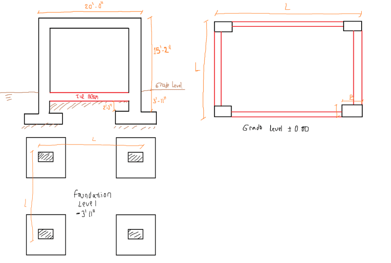
I have a moment-resisting concrete frame structure located in a high seismic hazard zone. At the base or ground level, I will place a tie beam that will be connected to pedestals (or fully buried column sections that allow the foundation level to be reached) (see attached image).

Considering that the pedestals comply with the H/d < 3.0 ratio, and taking into account the provisions of ACI 318 18.2.2.3, which states that "any element below the base required to transmit seismic forces must comply with the provisions of Chapter 18", I'm wondering follow:

- Should the pedestal be considered as an element subjected to axial load and bending, as those defined in 18.7?
- If so, should the design shear force (Ve) be satisfied, as described in 18.7.6.1, where the shear force must be calculated considering the maximum probable moments at the faces of the joints and the unsupported length of the pedestals!!!?
- In my opinion, it is not necessary to calculate the design shear force in the pedestal as if it were expected to dissipate energy. Because the pedestal, being buried and having a low H/d ratio (less than 3), behaves more like a rigid body than a flexible element. Also,the main function of the pedestal is to transmit the axial force of the column to the ground and the shear force transfer between the pedestal and the ground is mainly done by friction. In my experience, I have designed pedestals in this way without performing the design shear force calculation as defined in 18.7.6.1, and I have not found any problems.
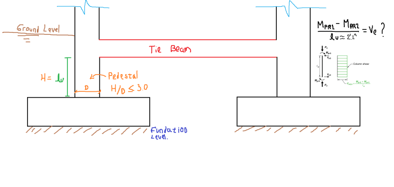
Pedestals_tytizv.png


I appreciate any comments or suggestions you may have regarding this.
 
Replies continue below

Recommended for you

You did not provide a lot info. here..
Definition of pedestal; member with a ratio of height-to-least lateral dimension less than or equal to 3 used primarily to support axial compressive load; for a tapered member, the least lateral dimension is the average of the top and bottom
dimensions of the smaller side.
IMO, the stiffness of pedestal should be 5- 10 times of the supported column such that , the column could be modelled fixed on the pedestal.

The sketch that you posted implies column sizes and pedestal sizes are the same.

My points ;

- Tie beams should be located at isolated footing/pile cap level and not be tied to a column at any intermediate level
which can result in a short column.
- The perimeter grade beams in your case , if they extend to the top level of ftg, the perimeter columns will be short columns and will attract greater forces,
- Typical tie beam dimensions 8 to 10 in. and designed for axial loads ( tension and compression ) and will nor justify to assume a cellar level.

You may provide more info. structural plan,foundation plan , no. of storeys , seismicity .. to get better responds.


According to the grace of God which is given
unto me, as a wise masterbuilder, I have laid the foundation, and another buildeth thereon. . . .
I Corinthians 3:10
 
HTURKAK said:
You did not provide a lot info. here..
Definition of pedestal; member with a ratio of height-to-least lateral dimension less than or equal to 3 used primarily to support axial compressive load; for a tapered member, the least lateral dimension is the average of the top and bottom
dimensions of the smaller side.
IMO, the stiffness of pedestal should be 5- 10 times of the supported column such that , the column could be modelled fixed on the pedestal.

- Regarding the info, I created new figures in response to your request. However, I believe they might not be essential for your understanding.

Pedestals2_ptilcs.png


- Regarding the pedestal, the elements shown are pedestals to me. While their primary function is to resist axial loads, they can also transmit lateral loads (shear and moment).
- I am confident that the pedestal's stiffness is 10 times or more greater than the column above due to its significantly shorter length.

HTURKAK said:
The sketch that you posted implies column sizes and pedestal sizes are the same.

- Indeed, the only difference is in height. However, the same principle applies when larger dimensions are necessary for the pedestal.

HTURKAK said:
- Tie beams should be located at isolated footing/pile cap level and not be tied to a column at any intermediate level
which can result in a short column.

- It is not mandatory for the tie beam to be at the footing level. The pedestal and the footing, being buried and due to the stiffness of the pedestal, can be considered, together with the footing, as a single foundation element.

HTURKAK said:
- The perimeter grade beams in your case , if they extend to the top level of ftg, the perimeter columns will be short columns and will attract greater forces,

- It is not only a perimeter tie beam, all the columns are tied at that level, with tie beams. It is unlikely that they will attract more forces (short column effect), since there are no slender columns at ground level, but pedestals with the same or similar free height.

HTURKAK said:
- Typical tie beam dimensions 8 to 10 in. and designed for axial loads ( tension and compression ) and will nor justify to assume a cellar level.

- While I agree with your point, some might consider combining tie beams and pedestals as a new level in structural models. However, I believe this interpretation is inaccurate due to the expected failure mechanisms in these structures. I mean that we cannot expect a failure in a pedestal or footing.

Nevertheless I still have the concern about ACI 318 18.7.6.1, because code requires determining the design shear force from probable moments. I consider this to be unreasonable for pedestals, whose function is to transmit forces, not dissipate energy through plastic hinges.


Thanks for your answer.
 
Hi everyone, if anyone has any new thoughts on my problem, I'd really appreciate your input. Even if it means telling me I'm wrong, just that I don't know how haha. I'm all ears!.
 
I'm not American so I can't speak to any clauses of ACI etc. However, I work in a high seismicity country, so I expect our philosophies for design to be generally similar.

I'm assuming that you have a ductile system - presumably dissipating energy at the beam-column joint at first floor (hinging in the beam?)
If so, I would expect that your beam overstrength shear and moment would be transferred into the joint then the column.
This would generate large axial forces in the column that I expect would be transferred to your pedestal base.

The question of lateral load I'm a little confused about as I'm not sure whether you have dirt between the buried pads or open space (car parking?).
However, my general thought is that you SHOULD be designing the pedestal as a separate level in your model
This feels similar to a podium wall structure, where you end up with large shears at the podium level

In your case, I think you have two scenarios:

1) All base shear is resisted at the 'Foundation Level' shown in your plan
The tie beam actually acts as another moment-resisting frame and you'd need to consider this in your model as a potential hinge point
You'd need to consider this accurately as it will be very different from your current model, but you will end up with large overstrength moments and shears in your pedestal level
The moment capacity of your foundation will also need to be considered in your model - as it is quite wide, it will have some overturning capacity, particularly with the dirt sitting on it
If you don't get these values in your model then you will overestimate your ductility and will generate larger forces than expected, including potentially adverse failure modes

2) The 'Ground Level' shown in your plan is sufficiently stiff (and the dirt is infilled around the tie beam?) that most/all lateral load gets taken out at this level
The pads at 'Foundation Level' only take overstrength axial loads from your first floor column hinges
However, for a ductile design you need to follow the overstrength loads through the system
Your 'tie beam' is now actually a grade beam transferring the beam overstength forces tracked through the column
So your pedestal has primarily axial loads but your grade beam gets hammered

I think (1) is the more accurate model (particularly as I think there's no dirt around the tie beam..?)
Regardless, I think any attempt to ignore the pedestal due to 'H/D < 3' or whatever is an oversimplification
I think you need a more detailed analysis - this is a more complex system than you're trying to simplify it to
 
Thank you for your response, I will try to provide information or observations about it.

Greenalleycat said:
I'm assuming that you have a ductile system - presumably dissipating energy at the beam-column joint at first floor (hinging in the beam?)
If so, I would expect that your beam overstrength shear and moment would be transferred into the joint then the column.
This would generate large axial forces in the column that I expect would be transferred to your pedestal base.

You are correct, the seismic resistance system above the tie beam level (buried beam) is a ductile moment-resisting frame system.

Greenalleycat said:
The question of lateral load I'm a little confused about as I'm not sure whether you have dirt between the buried pads or open space (car parking?).
However, my general thought is that you SHOULD be designing the pedestal as a separate level in your model
This feels similar to a podium wall structure, where you end up with large shears at the podium level

I understand your point, but from a structural analysis perspective, I don't fully agree. Since the pedestal is a rigid element, it cannot be considered a slender element and therefore does not buckle. In other words, there is no significant deformation, so the load transfer would be complete. On the other hand, the beam is fully supported, and for it to work in flexure, the pedestal would have to deform, which does not happen because it is a rigid element. So my question would be... in what scenario do you consider the pedestal as an element that can achieve double curvature or that can present two plastic hinges (at the top and bottom)?

Greenalleycat said:
I think (1) is the more accurate model (particularly as I think there's no dirt around the tie beam..?)
Regardless, I think any attempt to ignore the pedestal due to 'H/D < 3' or whatever is an oversimplification
I think you need a more detailed analysis - this is a more complex system than you're trying to simplify it to

In my opinion, Model 2 is more reasonable. However, the tie beam is not a rigid enough element for the deformations transmitted to the ground to affect it to the point of considering it an element with high ductility. They only guarantee the integrity and brace the pedestal level, the tie beams only function as tensors. In my opinion, it is only reasonable to consider the resultant forces of the structure at the top base of the pedestal, apply the overstrength factor to them, and ensure that the pedestal only by itself can transmit these forces without yielding or failing to fundation.

Also consider a 1m x 1m square column with a height of 1m. How can you make this element ductile when you cannot apply Euler's theory since it is not slender?
 
I'm not really understanding your point. Whether something is 'slender' or not is a human definition, not an engineering one
The pedestal does deform - everything does when you apply load to it
To our eye, that deformation will of course be negligible because of the element's aspect ratio, yes, but it's still proportional to load carried
Double curvature just refers to being able to develop moment capacity at both top and bottom, which your element has limited capacity to do - the limitation being the moment capacity of the footing
Maybe it is a shear dominated element - but you still need to calculate actual moment and shear demands on it and design it as appropriate


Greenalleycat said:
I'm not really understanding your point. Whether something is 'slender' or not is a human definition, not an engineering one
The pedestal does deform - everything does when you apply load to it
To our eye, that deformation will of course be negligible because of the element's aspect ratio, yes, but it's still proportional to load carried
Double curvature just refers to being able to develop moment capacity at both top and bottom, which your element has limited capacity to do - the limitation being the moment capacity of the footing
Maybe it is a shear dominated element - but you still need to calculate actual moment and shear demands on it and design it as appropriate

First, thanks for the reply

I agree that everything deforms, and perhaps I am mistaken in expressing it in words, what I tried to say is that a rigid element does not buckle, it is not likely to fail by buckling, much less achieve a condition in which plastic hinges are generated at its ends.

In structural engineering (analysis and design), the definition and distinction between slender and rigid elements are crucial for understanding their behavior and designing these structures. A rigid element would never buckle, as to apply Euler's theory. And it is precisely what I am trying to clarify, how a rigid element (such as a pedestal) can generate a double plastic hinge (at its top and bottom), to be able to assume that the design shear will be that which is generated or derived from the probable moments of plastification at its ends?

On the other hand, I guarantee the transmission of all the loads from the base of the column that rests on the pedestal to the footing or foundation, and in fact these loads are amplified by the overstrength factor (hoping that this element will never fail under such loads), because the ideal is that my fuse or ductile element is the column, not the pedestal. Now, what I am trying to do is justify myself for not applying the design shear required in ACI318 18.7.6.1, because I clearly do not understand how I can demand that an element, such as the pedestal, fail as if it were a column that has the possibility of generating plastic hinges at both ends?

Again thanks for the time you take and reply, it helps me.
 
I don't see your link between buckling and ductility
Ductility relates to the moment demand on the element and the level of steel reinforcement provided
If you take a big block of concrete and only put one piece of steel at each end, you will generate a ductile flexural demand on that steel as you push it

Taking a step back, the more important thing is to get the boundary conditions correct on your model as that will determine what load exists on each element
You need to model the whole structure and then realistically model where your base shear and axial load resistance is coming from
Once you do that you will see what the demands are on your structural elements including the podium
 
Greenalleycat said:
I don't see your link between buckling and ductility
Ductility relates to the moment demand on the element and the level of steel reinforcement provided
If you take a big block of concrete and only put one piece of steel at each end, you will generate a ductile flexural demand on that steel as you push it

Taking a step back, the more important thing is to get the boundary conditions correct on your model as that will determine what load exists on each element
You need to model the whole structure and then realistically model where your base shear and axial load resistance is coming from
Once you do that you will see what the demands are on your structural elements including the podium

You're absolutely right. I generally associate the ductility of an element with its ability to dissipate energy, in other words, the ability of an element to achieve a plastic hinge, or for the steel to yield. A double plastic hinge is structurally desirable and is likely to occur in a slender column, ensuring that it does not fail in shear... But in a pedestal, considered rigid, is this likely? For that curvature to occur in a column, it must be susceptible to buckling conditions, and in rigid elements this does not happen, because precisely the material yields before geometrical instability of the same is achieved.

So I ask again, how is it possible that a 1m x 1m x 1m pedestal could exhibit a double plastic hinge, in order to ensure the design shear that arises from the probable plastic moment of both ends?

Thanks for reply
 
Well, you said that your system is ductile hinging in the beams not in the columns
Double hinging in columns is not a favourable failure mechanism as that is a soft story/collapse mechanism

In a beam sway structure everything else should be capacity protected against that mechanism by tracking overstrength loads through the structure
You then provide sufficient strength to meet the overstrength shear and overstrength moment capacities in your pedestal column
What you need to be careful of here is that, if you only track the hinging loads from your top story, you may underestimate these demands due to the additional frame at the ground floor
This frame will have a surprisingly large impact on your structure, particularly on your building period as it will massively stiffen your building

I still do not understand your point about the column ductility vs buckling
a 1m x 1m x 1m pedestal could exhibit a double plastic hinge if it was sufficiently reinforced against shear to allow its moment capacity to be achieved
Given that shear and flexural reinforcement are largely independent of each other, this seems quite plausible to achieve

 
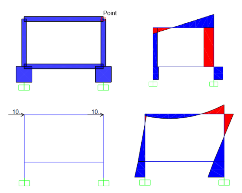
I don't know how exactly you've modelled this thing, but to illustrate the point on why you need to include the bottom layer, here is an arbitrary representative frame I've modelled
I've shown 4 cases - a pin-based sway frame, a sway frame with an additional member at ground level with fixed connections to the columns, and a 3rd model with a 1m extension below ground and a beam at ground level, and a final case where you have the beam at ground level and the lateral load resistance at ground level

As you can see, all 4 cases give you different deflections (hence, periods, hence varying seismic loads) and also have very different moment/shear demands
Make sure you consider carefully where the resistance is in your building

Screenshot_2024-05-13_144324_pf8qkz.png
Screenshot_2024-05-13_144710_bgaiqs.png
Screenshot_2024-05-13_144725_x74aws.png
 
Greenalleycat said:
Well, you said that your system is ductile hinging in the beams not in the columns
Double hinging in columns is not a favourable failure mechanism as that is a soft story/collapse mechanism

In a beam sway structure everything else should be capacity protected against that mechanism by tracking overstrength loads through the structure
You then provide sufficient strength to meet the overstrength shear and overstrength moment capacities in your pedestal column
What you need to be careful of here is that, if you only track the hinging loads from your top story, you may underestimate these demands due to the additional frame at the ground floor
This frame will have a surprisingly large impact on your structure, particularly on your building period as it will massively stiffen your building

I still do not understand your point about the column ductility vs buckling
a 1m x 1m x 1m pedestal could exhibit a double plastic hinge if it was sufficiently reinforced against shear to allow its moment capacity to be achieved
Given that shear and flexural reinforcement are largely independent of each other, this seems quite plausible to achieve

No, precisely... the failure mechanism has a structurally favorable hierarchy: the beams plastify first, and then the columns plastify... however, columns in high seismic threat zones should be highly ductile, meaning they should be able to develop a double plastic hinge. In order for the probable moment (at which the section yields and generates a plastic hinge) to occur, there will be an associated shear force, which we call the design shear (Ve, ACI318). Now the most unfavorable condition is when the moments at the ends are opposite, and if you look at the first image I posted, the shear associated with that condition is very large since the free length is too short. Now what I am trying to answer is if this is possible, that in a pedestal, which can be considered rigid element, is it possible for it to plastify at both ends? And if so, how is this achieved, if Euler's theory does not apply to rigid elements? For me and for most people, (I would think, maybe I'm wrong), a rigid element fails by material yield, not by buckling (the double curvature that occurs in plastic hinges).

In other words, I'm trying to justify the design shear (Ve), associated with the probable plastic moment (Mpr + and -), at both ends (opposing sign moments), which shall be used in pedestals or extremely rigid elements, which are designed and expected to never reach failure under the demanded forces. In other words, all the columns should plastify first, lose all their flexural capacity, reach instability, collapse, and even then the pedestal would not have failed. So why does the code seem to require this to be used in rigid elements? :/
 
Antidude90 said:
No, precisely... the failure mechanism has a structurally favorable hierarchy: the beams plastify first, and then the columns plastify... however, columns in high seismic threat zones should be highly ductile, meaning they should be able to develop a double plastic hinge. In order for the probable moment (at which the section yields and generates a plastic hinge) to occur, there will be an associated shear force, which we call the design shear (Ve, ACI318). Now the most unfavorable condition is when the moments at the ends are opposite, and if you look at the first image I posted, the shear associated with that condition is very large since the free length is too short.

I'm with you through all of this and agree

Antidude90 said:
Now what I am trying to answer is if this is possible, that in a pedestal, which can be considered rigid element, is it possible for it to plastify at both ends? And if so, how is this achieved, if Euler's theory does not apply to rigid elements? For me and for most people, (I would think, maybe I'm wrong), a rigid element fails by material yield, not by buckling (the double curvature that occurs in plastic hinges).

I really don't understand what you mean here. Which Euler theory are you referrring to here - column bucklung under axial load..?
When you say rigid, are you meaning rigid as in 'no lateral deflection of the element' or 'no rotational deflection at the joints'?
I'm very confused why you refer to 'double curvature that occurs in plastic hinges' as buckling...can you please clarify this for me

Antidude90 said:
In other words, I'm trying to justify the design shear (Ve), associated with the probable plastic moment (Mpr + and -), at both ends (opposing sign moments), which shall be used in pedestals or extremely rigid elements, which are designed and expected to never reach failure under the demanded forces. In other words, all the columns should plastify first, lose all their flexural capacity, reach instability, collapse, and even then the pedestal would not have failed. So why does the code seem to require this to be used in rigid elements? :/

I'm completely lost through here. Perhaps this is a regional/code difference. Your design demands on the columns and pedestal should all be derived from the overstrengths of the beams followed through. This shouldn't produce unreasonable reinforcement requirements?
 
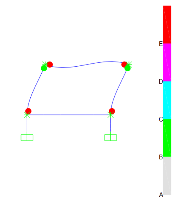
The models are fine, I would model with the condition that the pedestal has a higher stiffness, or that the tie beam is very flexible compared to the pedestal, thus I would obtain results more similar to those I show you in the image.
image_2024-05-12_222517293_r4h2qo.png


However, the model does not answer my question, because it is focused on the failure mechanism, that is, taking your structure to collapse would show you how plastic hinges are likely to be generated with a pushover analysis, and how you see the columns and beams would lose all their capacity and the pedestal or tie beam would not even feel any damage.
image_2024-05-12_223715503_ykb4vw.png
 
Not exactly my field, but you can’t magically declare something “rigid” and then claim it can’t fail. Real structure has no idea that someone declared a portion “rigid” and avoids failing there. Need to back up from the modelling idealization world into the real messy world.
 
Greenalleycat said:
I really don't understand what you mean here. Which Euler theory are you referrring to here - column bucklung under axial load..?
When you say rigid, are you meaning rigid as in 'no lateral deflection of the element' or 'no rotational deflection at the joints'?
I'm very confused why you refer to 'double curvature that occurs in plastic hinges' as buckling...can you please clarify this for me

When a column reaches its plastic hinge, it means that it loses its flexural capacity, causing lateral displacements to increase and making it susceptible to geometric instability (buckling). This condition favors the appearance of more plastic hinges and, consequently, greater energy dissipation. So, how is it possible in a pedestal?

Greenalleycat said:
I'm completely lost through here. Perhaps this is a regional/code difference. Your design demands on the columns and pedestal should all be derived from the overstrengths of the beams followed through. This shouldn't produce unreasonable reinforcement requirements?

In design, when we talk about Probable Moment (Mpr), it is the moment at which your section fails (generates a plastic hinge or the material yields). To reach that moment, certain conditions must be met, such as an increase in shear in proportion. In the analysis results, the shear may be X, but when using the equation to determine the shear associated with the probable moment, it is very reasonable to expect a shear greater than the X given by the model. It is a way of ensuring that your column or beam will reach a plastic hinge and that it will not fail in shear before that.
 
SWComposites said:
Not exactly my field, but you can’t magically declare something “rigid” and then claim it can’t fail. Real structure has no idea that someone declared a portion “rigid” and avoids failing there. Need to back up from the modelling idealization world into the real messy world.
It's not that I'm magically declaring something rigid just because I want to. There's an aspect ratio that defines whether an element behaves rigidly or flexibly. I'm not saying that it won't fail magically; I'm literally using a multiplier factor of 2.0 to ensure that the element behaves elastically to withstand the demanded forces associated with the supported structure, even exceeding the ultimate forces (moment and shear at plastification) of the supporting column base.

But as I said before, the ACI318 code requires that this element (rigid pedestal) also plastify like a slender column, and that's where I disagree or seek an explanation.
 
Antidude, if you do form the failure mechanism that you propose then you would need to capacity protect your whole podium/pedestal structures (tie beam and short columns)
i.e. designing them to be stronger than the overstrength of the beam sway mechanism that you've shown
Is that what you have done/are intending to do?

Antidude90 said:
When a column reaches its plastic hinge, it means that it loses its flexural capacity, causing lateral displacements to increase and making it susceptible to geometric instability (buckling). This condition favors the appearance of more plastic hinges and, consequently, greater energy dissipation. So, how is it possible in a pedestal?
That definition of Mpr is consistent with here, yes
When it reaches Mpr it hasn't failed though - in a system detailed for ductility it just means that you resist further shaking through energy dissipation rather than elastic deformation
As to how that can form in a pedestal - simply, if you provide insufficient strength in the tie beam + pedestal short columns
This goes back to my point above - these elements should be capacity protected against your failure mechanism

Antidude90 said:
The models are fine, I would model with the condition that the pedestal has a higher stiffness, or that the tie beam is very flexible compared to the pedestal, thus I would obtain results more similar to those I show you in the image.
Is this realistic? What are the dimensions of your various beams and columns

 
Greenalleycat said:
Antidude, if you do form the failure mechanism that you propose then you would need to capacity protect your whole podium/pedestal structures (tie beam and short columns)
i.e. designing them to be stronger than the overstrength of the beam sway mechanism that you've shown
Is that what you have done/are intending to do?

That is exactly what I did... but as I mentioned, ACI 318 18.2.2.3 states the following: "any element below the base required to transmit seismic forces must comply with the provisions of Chapter 18" which means that I must comply with seismic detailing and design loads. In other words, detail a pedestal as if it were going to exhibit a double plastic hinge (ACI 318 18.7.6.1), and this irrationality (in my view) is what I am trying to resolve.

Greenalleycat said:
That definition of Mpr is consistent with here, yes
When it reaches Mpr it hasn't failed though - in a system detailed for ductility it just means that you resist further shaking through energy dissipation rather than elastic deformation
As to how that can form in a pedestal - simply, if you provide insufficient strength in the tie beam + pedestal short columns
This goes back to my point above - these elements should be capacity protected against your failure mechanism

Of course, if I wanted my pedestal to behave as an energy-dissipating element, I could do so by reducing its stiffness and ensuring that it behaves as a slender element... but that is not convenient. In what situations does one perform a structural design expecting a pedestal to have energy dissipation capacity? In my view, I would never do that. Now, in my particular case, how can I achieve that a pedestal, designed for the overstrength forces of the columns, has energy dissipation capacity? And considering that its behavior is more similar to that of a rigid body than that of a slender column, I still do not find a reasonable argument for it.

Greenalleycat said:
AIs this realistic? What are the dimensions of your various beams and columns
Tie beams are only designed to resist a portion of the vertical load as axial load (0.1Sds). And generally, the shortest section must have a minimum dimension equal to the clear span divided by 20. This makes tie beams not very rigid compared to other elements that make up the seismic resistance system. Therefore, if you include them in your model, they will not significantly affect the distribution of forces.

Thanks for reply.
 
Status
Not open for further replies.

Part and Inventory Search

Sponsor