Continue to Site

Eng-Tips is the largest engineering community on the Internet

Intelligent Work Forums for Engineering Professionals

  • Congratulations SSS148 on being selected by the Eng-Tips community for having the most helpful posts in the forums last week. Way to Go!

Setting up Datums, and controlling the orientation of a datum simulator or measurement

Status
Not open for further replies.

Nereth1

Mechanical
Feb 2, 2014
136
Hi all,

I have a fairly simple problem I think, but I am new to this and I think I am missing something basic.

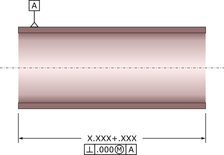
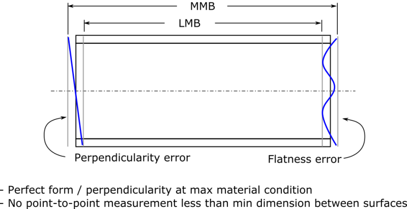
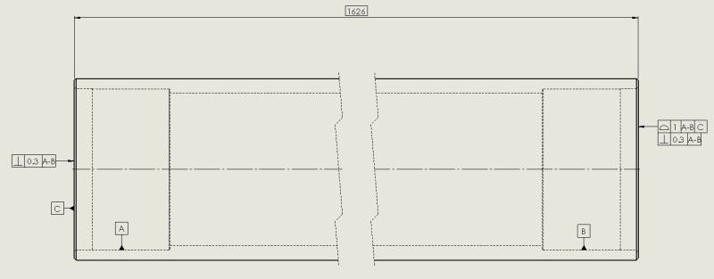
I have a simple tube that I am trying to control the length of. Its ends are cut to a certain perpendicularity to its own axis (I have a good set of datums that allow me to define a datum axis along the length of the part). They are not necessarily cut parallel to each other.

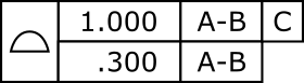
How do I set up a feature control frame to measure length along the length of the axis? If I put a datum on one end and set up a position tolerance on the other, relative to that datum, then the datum simulator will end up taking up the angle of the lack of perpendicularity of the end it is on, and therefore the tolerance zone will do the same thing on the other side. That throws out the measurement.

Is there a way to reference the datum axis in order to 'measure along it'?

I definitely feel like I am missing something basic in the theory of setting up Datums for a part. I think I will be taking Y14.5 home with me over the weekend.
 
Replies continue below

Recommended for you

Is this what you're trying to do? (See attached)
download.aspx
 
I'm not sure - does applying the length tolerance between the two perpendicularity controls indicate that the length tolerance must be measured perpendicular to those? If so, can you point me to what section of Y14.5 explains doing it that way?

What I want is roughly seen in the attached. All of those green arrows must be within the tolerance specified, with all measurements taken along the blue axis.

What is the graceful way to achieve that?

I've been reading for the last hour and it's making me doubt everything I thought I knew about dimensioning. This can't be that hard!
 
 http://files.engineering.com/getfile.aspx?folder=dd4fd51a-4b2a-4a57-be89-468fb76abc21&file=pipe_spec.png
My interpretation is:
For a feature of size, you have perfect form at the maximum material boundary per Rule #1. So, in this case at MMB the cuts in the pipe are perfectly perpendicular and flat. As you deviate from the MMB, you can have error in perpendicularity, flatness, etc. No point to point measurement can violate the least material boundary for the dimension.

Hopefully someone will correct me if I'm wrong.

Please note the correction below.
 
Rule #1 (perfect form at MMC) does not control orientation as it appears flash3780 is thinking.

Another way might be:

Datum B could be assigned to one end of the tube with a perpendicular orientation control relatived to datum A.

A basic dimension from datum B to the opposite end.

A Profile geometric control could then be assigned to the opposite end of datum B, using datum A & B as a DRF (Datum Reference Frame)

Profile controls: form, orientation, size and location.

Something to consider....
 
dtmbiz is correct. Para 2.7.3 of ASME Y14.5-1994 clearly states that orientation is not controlled by the limits of size. So at MMC the part drawn in my post above could be out of square by the perpendicularity tolerance. When I stop to think about it, this is consistent with how you handle perpendicularity in a stackup -- as an independent control.

To achieve a part which is, in fact, perfectly square at the MMB, you can do the following (see attached/below):
tube1_bvxy3c.png


So, in this case at MMB the cuts in the pipe are perfectly perpendicular and flat. As you deviate from the MMB, you can have error in perpendicularity, flatness, etc. No point to point measurement can violate the least material boundary for the dimension.
 
You can also read up on the dimension origin symbol. That might be the easiest way, since your main objective seemed to be just measuring length.

John-Paul Belanger
Certified Sr. GD&T Professional
Geometric Learning Systems
 
flash3780,

Don't quite believe you have captured the OP's concern with this latest post.

The latest post shows that you are holding the "center plane" with a perpendicular control to Datum A;
which will not control the end surfaces beyond the size limits. You have identified a feature of size
and not the end surfaces.

Your first post was fine. You could use a parallel control to relate both ends to each other, however
you would need to identify one or the other end as a Datum to reference.
 
In the very first post OP said that he wanted to measure length of the pipe along the datum axis.

This can be achieved be a text note similar in meaning to the note given in para. 4.4 of Y14.5M-1994 (it would just involve single datum axis for that specific length dimension).

Much more "elegant" way would be to follow dtmbiz's suggestion (with a profile callout referencing to A|B).

But there is one thing to remember - these two options will not result in the same size of maximum material boundary (envelope) perpendicular to datum axis A, containing the pipe produced at maximum possible length and at maximum possible orientation error to datum axis A.
 
Could someone clarify how you would actually measure the length of a centerline of a hollow section and how to derive the 'correct' center points of the end faces.

_________________________________________
NX8.0, Solidworks 2014, AutoCAD, Enovia V5
 
I think my second post should do the trick if you want to have perfect form and orientation at MMC. However, tight orientation control might be a manufacturability concern if your length dimensions is small. You can certainly further control the individual faces with perpendicularity callouts if desired.

Another thing worth considering is whether the datum could be referenced at MMB. If so, the part could be measured with a height gage after sliding it into a vertical tube-shaped datum simulator (getting back to the original question about measurement).

Anyhow, here is an illustration of the control that I specified above:
tube3_qddyom.png


I suppose that I'd need some clarification if that's not what the OP is looking for.
 
Hi Guys,

I have read your responses and understood what I could - I suppose the issue I am having is that the perpendicularity tolerance I am using is quite large compared to the position tolerance (roughly half of the position tolerance is available for perpendicularity, on each side), This is compounded by the fact that the pipe is quite long compared to its width, so if an off square end is brought up against a flat datum simulator, then the normal distance to the end from the datum simulator becomes very different than the distance along the pipes axis.

I have thought about this, and I can control it if I can specify that the datum simulator be perpendicular to the parts axis. This is all possible with the physical part but the question is, how can I actually specify it with GD&T? I have a theory that I haven't used before as I am new to this, please see below:

I have previously seen, and not understood, tolerances given with respect to Datums that they cannot be measured from, for example, a hole position referenced from a datum plane perpendicular to its axis. Having just done some reading of Y14.5, it appears that what these datums serve to do, is to require the latter referenced datums to be set up in a particular way to create 3 orthogonal planes for the reference frame.

Therefore, here is what I want to do:

1) Datum axis established along the pipe based on bearing finishes on the pipe. This is what we want to measure along.
2) Datum on the face of one side of the pipe
3) Other side gets a positional tolerance with the primary datum being the axis of the pipe, and the secondary datum being the other face of the pipe.
4) Both sides get there own perpendicularity tolerances relative to the axis.

In theory this means the datum feature simulator for the secondary datum needs to be perpendicular to the axis of the pipe (first datum), and then brought in to touch the edge of the pipe. Does this all sound like it should work?

Thanks.
 
I'm not sure that I follow where position tolerance comes into play. Perhaps you could post a sketch, or explain what you're trying to do functionally? If we understood the design limits better we could make better suggestions.

If you're only concerned about size relative to the axis of the cylinder and not the end condition, I think that you might consider using the zero perpendicularity error on the centerplane of the end cuts at max material condition. That way, your pipe will never be longer than the maximum size dimension or shorter than the minimum size dimension along its axis.
 
What you are looking for is to control the profile of the pipe ends relative to its axis. There is a symbol for that.

You can base the profile of each end wrt to the axis and a datum plane touching the opposite end; there will be a basic dimension between them.

There isn't a control in 'Y14.5 for the orientation of a two point measurement, though you can create your own note to describe the measurement method you want.

The use of a perpendicular face in a typical position tolerance is because the primary controlling factor for position is the orientation of the feature; then the location relative to some other feature. Position is also not applicable to planar surfaces.
 
Until just now, I actually didn't realize position was not applicable to planar features. I was avoiding using profile tolerance because I didn't think it was necessary for a flat plane, but now that I have had another look, indeed position can't apply the way I intended it and profile will be necessary.

3DDave, I agree that it seems a profile tolerance on one end with primary reference being the axis and secondary being the datum on the other end, should do the job. This scenario is almost exactly out of figure 8-13 of Y14.5. It is what I had attempted with position tolerance so all I need to do is change to a profile symbol.

Thank you very much everyone, I think with your combined responses, it has been resolved, and more importantly I have learned a hell of a lot. I have included a drawing of the part with all the unrelated stuff removed, please let me know if you see any issues.


tolerancing_bjpg0a.jpg
 
It looks like you have a tighter constraint on perpendicularity than length in your design per the sketch you provided. Perhaps those faces are sealing against something. If so, what you've got should achieve that goal.

A couple of notes:
[ul]
[li] Controlling your pipe to +/- 1/64" probably cannot be accomplished by saw-cutting. You will need to mill that dimension or cut it on a lathe.[/li]
[li] Perpendicularity control of ~10 thou may also require milling or lathe cutting[/li]
[li] The RHS profile tolerance/perpendicularity combo looks like a good opportunity to use a composite profile tolerance instead.
tube4_liyuho.png
[/li]
[/ul]


* Items in red updated in accordance with comments below
 
Since there's a bore in each end that's apparently critical to function, I think it's safe to assume the length would be cleaned up during a turning/lathe operation that's also cutting those bores, and a saw would only cut it to a rough length rather than finish length.

_________________________________________
NX8.0, Solidworks 2014, AutoCAD, Enovia V5
 
I don't quite understand what do we need datum [C] for?

First, datum [C] implies that functionally left end of the part is somehow more important than right side.
Second, when you give real part to quality control guy, how will he know which side is datum [C]?

To me specifying Profile of a surface 1.000 wrt A-B and Total runout .300 wrt A-B on both sides should do the trick.

"For every expert there is an equal and opposite expert"
Arthur C. Clarke Profiles of the future

 
JNieman is correct, a lathe could also achieve the perpendicularity or profile tolerances. Actually, that's what they'll probably use. I just wanted to point out that saw-cutting is probably not going to work for those tolerances.

CheckerHater said:
To me specifying Profile of a surface 1.000 wrt A-B and Total runout .300 wrt A-B on both sides should do the trick.

I guess you might need Datum C to measure the length from; the two ends are independent features and get independent profile tolerances. I think it's needed.
 
Two ends are not independent features - they are tied together by basic dimension.

"For every expert there is an equal and opposite expert"
Arthur C. Clarke Profiles of the future

 
Status
Not open for further replies.

Part and Inventory Search

Sponsor