Continue to Site

Eng-Tips is the largest engineering community on the Internet

Intelligent Work Forums for Engineering Professionals

  • Congratulations cowski on being selected by the Eng-Tips community for having the most helpful posts in the forums last week. Way to Go!

Shear Deformation - Point Moment 7

Status
Not open for further replies.

Celt83

Structural
Sep 4, 2007
2,083
This is probably something that is very easy and I am way overthinking it.

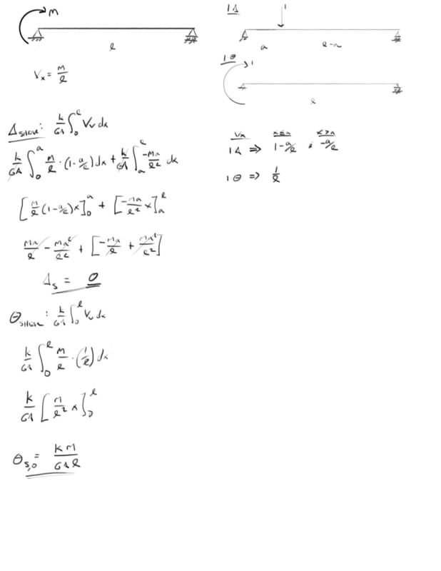
I've done the unit force method which shows that the shear deformation from a point moment is 0 at all locations on a simple span. I've done the same thing to show that the shear component of the slope at any location on the beam is constant = k M / A G L. Here is where I get hung up if the slope is constant and non-zero why is the deflection 0 from a math stand point, the mechanics make sense to me but I'm lost in the math on this one.

I have a great mechanics of materials book by Timoshenko and Young which for me so far has the best break down of shear deformations I've been able to find and in there they present that the slope due to shear is simply dy/dx = tau,max / G = k Vx / A G, which aligns with my unit method solution of k M / A G L.

integrating that once yields: y,shear = k M x / G A L + C1

Initial conditions are x=0, y=0 and x=L, y=0 the first condition yields C1 = 0, however the second condition yields C1 = k M / A G ... so I get that something is missing here which would should result in y,shear = 0 but I am at a loss.

would greatly appreciate any insight on this one.
2_e00mlq.jpg


Open Source Structural Applications:
 
Replies continue below

Recommended for you

IDS said:
Can you give some examples of applications where energy minimisation is the only tool for discerning how the world organizes itself?

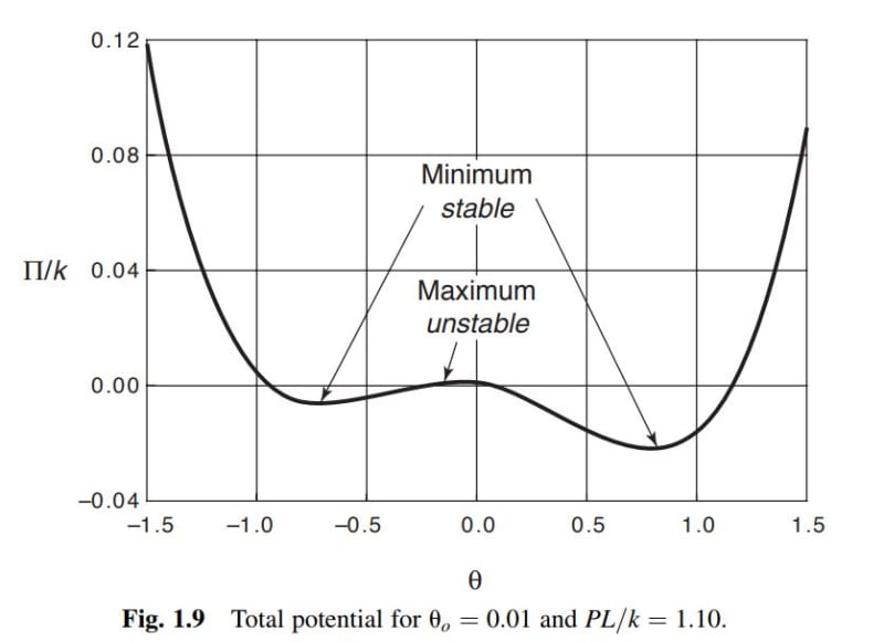
One example that comes to mind is dealing with non-trivial stability problems where bifurcation methods fall short. See the sketch below. I wouldn't say that energy methods are the only tool, rather, the only remotely convenient too that I'm aware of.

IDS said:
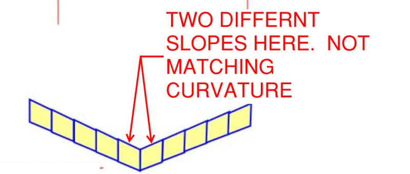
For your example of a point load at mid-span, the model with two different slopes in each half can't work because it results in the central section having two different slopes, but each section can only have one slope, since the beam is continuous.

I'm a bit confused by this. Looking only at the shear component of curvature, do we not normally have discontinuities of curvature? Option one -- the correct option repeated below -- also has two different slopes in each of the beam halves and in the central section. Regardless, to get hung up on continuity is to not entertain the crux of the mental experiment. The idea was to consider that:

1)in the real world, a discontinuity represents local damage that would consume energy needlessly and;

2)because of #1, materials organize themselves in a way that avoids discontinuities and;

3)1+2 = an explanation for why one type of shear strain -- longitudinal vs transverse -- might manifest itself at the expense of the other type. I selected this particular example because I don't believe that purely geometrical arguments offer an explanation here unless we're just going to keep falling back on the "discontinuities are invalid" thing without digging into it any more deeply.

c01_coy1wo.jpg


c02_ijwha9.jpg
 
KootK said:
4 May 19 17:37

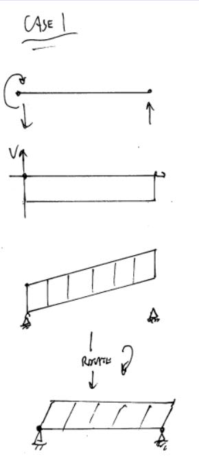
This sketch is not possible because you are showing negative shear deformation in response to positive shear. Positive shear will bring the top right corner closer to the bottom left corner, and will push the top left corner farther from the bottom right corner. This is true whether it's horizontal or vertical deformation. If you think about it, shear is neither "horizontal" or "vertical". Shear is just localized parallelograming (new word). The GLOBAL deflection of the beam due to shear might be vertical down or up, or horizontal left or right. But it's not "vertical" shear strain or "horizontal" shear strain. It's just shear strain. The global deflection is due to the new parallelogrammed shape meeting boundary condition requirements.


KootK said:
4 May 19 18:11

Break that system down into components and analyze the balance of energy you see why it's not possible. It is a vertical external load applied, so the internal work done must be vertical.


Cal91 said:
This sketch is not possible because

Already rescinded that one a couple of day ago.

KootK said:
5 May 19 00:06. In trying to elaborate upon the concept below, I discovered my own mistake in it. As such, withdraw the kinky-beam shown below as a valid counter example to the notion that that a constant shear beam is straight edged top and bottom.

Cal91 said:
Break that system down into components and analyze the balance of energy you see why it's not possible. It is a vertical external load applied, so the internal work done must be vertical.

Well yeah, that's exactly my own argument from above:

KootK said:
I now have an energy based theory for why. Try this on for size, speaking only to shear deformation:

1) A load must do work that produces displacement at the load and in the sense of the load. A vertical point load on a beam must produce vertical shear displacement at the load etc.

2) When an end moment is applied to a beam, it can only do work if the the resulting shear strain at the end of the beam would produce a rotation at the end of the beam. And a shear strain can only produce a rotation at the beam end if the shearing strain results in horizontal relative displacement between the top and bottom of the beam. A vertical strain wouldn't result in end rotation of the beam.

3) 1 + 2 = a moment is always going to produce shear straining that results in horizontal straining.

The terms vertical straining and horizontal straining are too imprecise I think. The new, KootK law of shearing deformation should read as follows:

1) A transverse load will always produce a shear strain perpendicular to the axis of the member.

2) A torque load will always produce a shear strain parallel to the axis of the member.

I'm not saying that case is possible, it's not. What I'm saying is that energy is my favorite, and occasionally only, tool for explaining why it's not possible.


I guess then I don't understand what anyone is confused about!
 
On my end, I'm just:

1) Interested in the hows and whys of this and;

2) Trying to provoke interesting discussion.

While I'm not certain of many things here, I also would not describe myself as being presently confused.

For me, this thread has really been my first ever, serious exposure to non-transverse shearing strain. It's come as a revelation to me and I've enjoyed exploring it. As is often the case, however, perhaps I've pushed it a bit far. Most of my colleagues here seem to currently be satisfied with what they know and how they know it. What are you gonna do through? Somebody's gotta be the last guy on the bus.

 
Haha I am with you on that. It has been a very enlightening thread to read, and I'm very appreciative of everyone's discussion as I have learned much. I didn't mean to be condescending in saying "confused". I was just curious if there was anything that wasn't resolved that I could help dig into. I feel like a freeloader sometimes, benefiting from the efforts of others on threads like these where I am actively reading but not contributing.
 
Cal91:

at the risk of adding additional confusion. My original problem was the text book I was using for a reference was stating that the slope was relative to the horizontal, see image in my post from 22 Apr 19 14:58.

so dy1/dx = tau,max/G = k*V / A*G, my initial confusion was performing the derivative of just this equation for a point moment yields a constant that:
a. had two values at the boundary conditions
b. was indicating a constant slope but 0 deflection. This was also part of my confusion because it yields a constant rotation of the cross-section and a 0 slope for the shear deflection component.

Digging further in I found that while dy1/dx is the slope of the deflection curve the rotation of the cross section is linked but not equivalent to this slope for a Timoshenko beam, where the rotation is linked to M = -EI d theta/dx and V = k/AG(-theta + dy1/dx). Performing the integration and substitution of both formulas shows a constant for the d theta/dx integration which solves to include a shear component, k/A*G or 1/k*A*G depending on preference for k, and that shear component cancels out during the integration of the dy1/dx formula.

When you perform those same integrations for a point load the constants for the rotation piece, d theta/dx, only include 1/EI components so no shear effect on the rotation, so the simplification made in the text reference that the slope = dy1/dx = k*V / A*G is valid because the theta shear component is 0.

Edit:
I'm right on the back of the bus with you KootK, it's all well and good that these calc out but I'd love to be able to draw a differential beam element and know that it will deform laterally or vertically.

Edit 2:
Full derivation for general point load and point moment Timoshenko formulas can be downloaded here: [URL unfurl="true"]https://github.com/open-struct-engineer/2DBeam/tree/master/Timoshenko/backupmaterial[/url]

Open Source Structural Applications:
 
Thanks for the explanation Celt. Shear deformation due to a point moment is an interesting problem indeed.
 
Yes, I'd forgotten about that. There is still this "need" on my end:

KootK said:
My ideal form of proof would be to be able to draw differential sheared elements, similar to what celt has done, and to be able to load and constrain them such that I could point to one or the other and be able to say "this one will shear transversely" or "this one will shear longitudinally". I feel that should be possible but don't yet know how to do it myself.

If Cal91 or anybody else has any ideas on that, I'd love to hear them.


Try this on for size fellow, back of the bus thought ninjas:

Hypothesis: in an extenally loaded thing, each and every strain in every element of that thing must contribute to the external load doing external work. Looking back to the example that we began with, every elemental strain in the beam has to make a contribution to rotation at the left end of the beam.

Do we buy that? If so, I might be able to take it somewhere...


Important correction:

Hypothesis: in an extenally loaded thing, each and every strain in every element of that thing must contribute to the external load doing external work. Looking back to the example that we began with, every elemental strain in the beam has to make a contribution to rotation of the vertical face of the left end of the beam (not the same as beam longitudinal axis rotation at the support).

 
Yes, this is what I'm trying to understand. When there's something CELT and KootK don't understand, you know you've got an interesting problem, that once you get to the bottom must be pretty enlightening. I'm just failing to see what it is, because from my viewpoint (and limited understanding) that has already been resolved.

KootK - when you say your ideal from of proof would be able to draw differential sheared elements, isn't this what you've already done on 22 Apr 19 16:39?

KootK said:

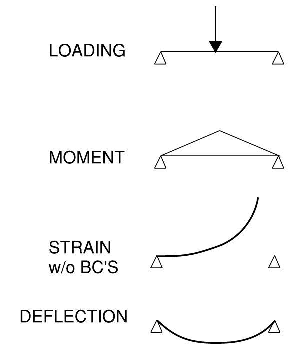
I don't see how this is any different than deflection due to bending in a simple beam. The differential elements are in compression in the top, tension in the bottom. This causes positive curvature, but alone it doesn't cause deflection upward or downward. It's only when the boundary conditions come into play that we get the full picture.

Compare KootK's sketch from 22 Apr 19 16:39 for shear deflection, to this sketch for bending deflection. Why are we all fine and good with the bending deflection, but we're hung up on the shear deflection from a point moment? I suspect it's only because we're so used to bending deflection, as that is what we see and understand, but the shear deflection is not intuitive and we don't see it because it's always masked by bending deflection. Yet the principles are the same. Am I missing something?

Capture_tx4sgl.jpg
 
Cal91 said:
KootK - when you say your ideal from of proof would be able to draw differential sheared elements, isn't this what you've already done on 22 Apr 19 16:39?

No. More this kind of stuff. I feel pretty good about things in macro now but I'd like to also have it in the bag en-micro as well.

Cal91 said:
it doesn't cause deflection upward or downward. It's only when the boundary conditions come into play that we get the full picture.

Yes! I very nearly posted an identical sketch identical to your last one when I was tearing it up with IDS about the validity of the geometric argument. I got to thinking the same thing. Namely, how it's odd that the rotation/superposition argument bothers me with shear but I accept the same thing for flexure without even thinking about it. My sketch was going to be a parabolic beam curve hovering above both supports magically but yours is better.

Cal91 said:
I suspect it's only because we're so used to bending deflection, as that is what we see and understand, but the shear deflection is not intuitive and we don't see it because it's always masked by bending deflection. Yet the principles are the same. Am I missing something?

No, I'd say that's pretty much it. I don't think that even conventional, transverse shear would have tripped us up here. As far as I can tell though, nobody saw the longitudinal only shear strain thing coming straight out of the gate.

c02_jlbfc2.jpg
 
KootK said:
Most of my colleagues here seem to currently be satisfied with what they know and how they know it. What are you gonna do through? Somebody's gotta be the last guy on the bus.

I for one, am not totally satisfied. When I read in my old "Elements of Strength of Materials" by Timoshenko and MacCullough the following:

Denoting by y1 the deflections due to shear, we obtain for any cross section the following expression for the slope:

dy1/dx = (sxy)y=0/G = kV/AG,

in which V/A is the average shearing stress sxy, G is the modulus in shear and k is a numerical factor by which the average shearing stress must be multiplied in order to obtain the shearing stress at the centroid of the cross sections.


I find it does not apply to the case described in the OP. The value of V is not zero, so the slope of the deflection curve is not zero...but it should be zero. Instead, the beam must be rotated to satisfy boundary conditions. This suggests to me that the elementary theory does not apply to the case being considered.

I have not followed through the proof provided by Celt83, but it should not be necessary to consider bending deflection in order to conclude that shearing deflection is zero.

BA
 
KootK said:
As far as I can tell though, nobody saw the longitudinal only shear strain thing coming straight out of the gate.

I don't think there is "longitudinal" shear strain vs "transverse" shear strain. It's all the same. Just shear strain. However, when you take the cumulation and apply the boundary counditions, you might have a longitudinal deflection, or a transverse deflection.

You are wanting to look at a differential element and differentiate between longitudinal strain and transverse strain, (I.E do the top and bottom sides slope while left and right sides remain vertical, or do the left and right sides slope while the top and bottom remain horizontal). But they are exactly the same in terms of strain. The strain has only to do with the angle between two sides departing from 90 degrees. The rigid body rotation of that element does not change the strain on the differential element. It's only after we apply boundary conditions that some sides might happen to be vertical, or horizontal, or sloped. You could even come up with a case where none of the four sides of the element due to shear deflection are parallel to a global axis. (A partially-fixed free cantilever beam where the partially-fixed end rotates some amount).

I don't know if I'm making any sense, or even if I'm right. But there's my thoughts.
 
BAretired said:
I find it does not apply to the case described in the OP. The value of V is not zero, so the slope of the deflection curve is not zero...but it should be zero. Instead, the beam must be rotated to satisfy boundary conditions. This suggests to me that the elementary theory does not apply to the case being considered.

I believe that simplified equation assumes that vertical faces of the beam remain vertical due to shear deflection. However in this case they do not. The slope that you would calculate from this simplified equation is exactly the rotation of the rigid body, and thereby complies with boundary conditions.

BAretired said:
I have not followed through the proof provided by Celt83, but it should not be necessary to consider bending deflection in order to conclude that shearing deflection is zero.

I thought we all agree on this, including Celt83? Does someone not?

 
cal91 said:
..I believe that simplified equation assumes that vertical faces of the beam remain vertical due to shear deflection....
This is the distinction that my Timoshenko and Young "Elements of Strength of Materials" makes.

The hidden derivation work in the quasi static section on the wikipedia page for Timoshenko beam theory is really the direction we are getting at I just don't remember my first principle stuff to that much detail and well also multi-variable calculus. Which on a cursory surface review of that work is getting into Kootk's energy theory and the hypothesis he posed.
[URL unfurl="true"]https://en.wikipedia.org/wiki/Timoshenko_beam_theory[/url]

Open Source Structural Applications:
 
cal91 said:
I believe that simplified equation assumes that vertical faces of the beam remain vertical due to shear deflection. However in this case they do not. The slope that you would calculate from this simplified equation is exactly the rotation of the rigid body, and thereby complies with boundary conditions.

I agree with your first sentence. The slope of the rigid body is zero, so the slope you would calculate from the simplified equation is the rotation of the vertical faces.

BA
 
Cal91 said:
I don't think there is "longitudinal" shear strain vs "transverse" shear strain. It's all the same. Just shear strain. However, when you take the cumulation and apply the boundary counditions, you might have a longitudinal deflection, or a transverse deflection.

I disagree with this and feel that there are indeed two distinguishable phenomena at play. For starters, transverse shear strain leads to transverse deflections whereas longitudinal shear strains do not. The angle so shear strain is the same for both cases but I don't believe that is the end of the story.


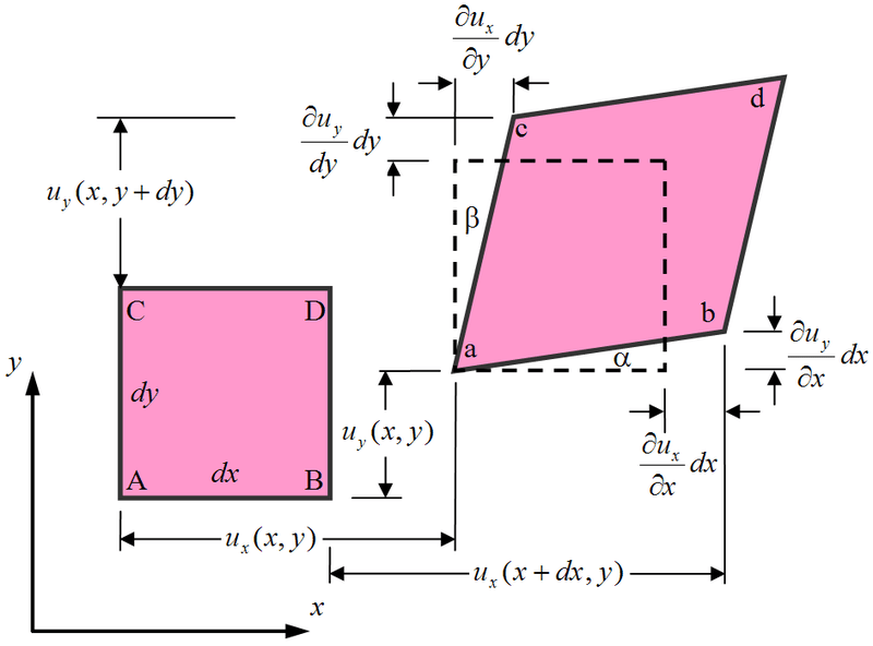
so looking at two-dimensional general deformation of an element:
800px-2D_geometric_strain_qguzsf.png

Image pulled from wikipedia to save a click:
[URL unfurl="true"]https://en.wikipedia.org/wiki/Deformation_(mechanics)[/url]

We are trying to get at why elements either collapse on alpha in the case of an applied external moment or collapse on beta in the case of vertically applied loads.

Open Source Structural Applications:
 
Status
Not open for further replies.

Part and Inventory Search

Sponsor