Pardon me if I am long-winded here.
Each technique is a means to determine the horizontal distribution of reactions at a given diaphragm level.
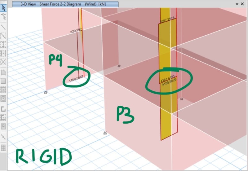
Rigid is basically the easiest to model mathematically.
Link
Each floor can be modeled as a series of three springs, one for each lateral direction, and a torsional spring. These springs are generated by summing up the stiffness of lateral elements first in each direction, then using a
polar moment of inertia to derive the spring constant for the torsional spring. Part of this process is determining the so called 'center of rigidity' this is the location on where applied shear loads in either direction
do not cause rotation of the slab. For seismic loading, the center of mass is also located, and any offset between the center of mass and the center of rigidity will cause an inherent torsional response. The code requires to consider the inherent torsion, plus an additional percentage of eccentricity due to 'accidental eccentricity' this is to account for unknowns when determining the center of mass. The overarching principle to consider is that the displacement of the rigid displacement of the slab must be 100% compatible with the displacement of the shear walls and columns. In other words, if the slab deflections 12" in the X-direction, then every wall/column attached to it must also deflect 12". There is no differential movement of the slab between lateral elements. Rotation of the slab complicates this a bit but its as simple as calculating the deflections due to direct shear, then combining it with deflections due to rotation.
The beauty of modeling a rigid diaphragm is that the slab itself is a
constraint not an element. This means you don't physically need elements to represent the slab, you don't need to worry about mesh of it etc (at least in terms of the horizontal distribution of forces). There are some downsides and oddities, some of which have been discussed here.
Flexible diaphragm is very much the opposite of rigid, the diaphragm offers zero relative stiffness between lateral elements. This method treats each diaphragm region between lines of lateral resistance as a simply supported beam. The reactions at the ends of the beams flow into the shearwalls based on statics of a simple beam. Since the diaphragm is modeled with zero stiffness, once the loads are into the walls, they cannot come out and go anywhere else (like your Original Post). This is a very common approach for wind and seismic in light frame construction, as well as metal deck roofs. My understanding is that computer programs essentially follow the same procedure that one would follow by hand, calculate the tributary width to a lateral line, determine the reaction based on statics of a simple beam.
Again as with rigid diaphragms, no actual FEA elements are needed to determine the horizontal distribution of forces.
Now finally the beast in the room. Semi-rigid diaphragms.
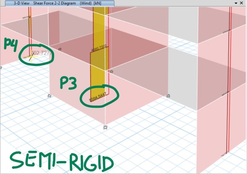
Semi-rigid is a loose way to refer to diaphragms modeled with their actual in-plane stiffness. In order to achieve this, FEA elements must be modeled and given proper material and section properties. They become part of the overall FEA model and are included in the global stiffness matrix. The loading is applied directly to the diaphragm elements themselves, and the results of the FEA give rise to the loading into the shearwalls/columns.
The difficulty here is mostly wrapped up in setting the material and section properties correctly. Depending on what design check your interested in, you may want more or less 'accurate' stiffness of the diaphragm to modeled. We had a good discussion about this recently that might help feed your mind on Semi-rigid a bit more.
[URL unfurl="true"]https://www.eng-tips.com/viewthread.cfm?qid=499735[/url]
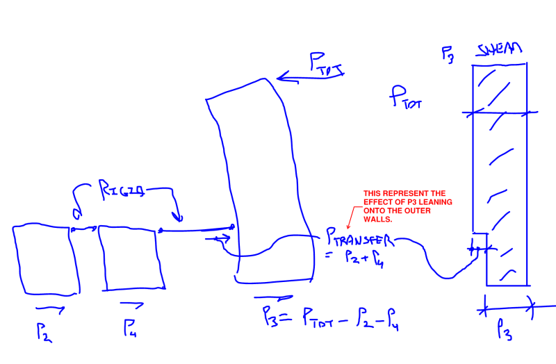
The semi rigid diaphragm may transfer loads around at floor levels like your original post, but compared to a rigid analysis the effects should be less pronounced.
On the design side of things, semi-rigid and rigid approaches generally take a bit more effort to determine things like diaphragm shear, drag-strut collectors, etc. With the flexible approach, the diaphragm shears and DSC forces are very easy to determine.