bulbamon
Structural
- Sep 12, 2022
- 9
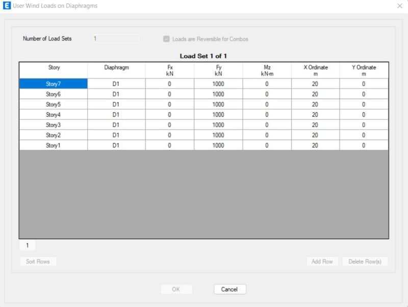
I have an example building consist of 7-story with 3 types of shear wall (P2, P3, and P4). I apply the same amount of lateral force each floor (1000 kN) using ETABS with rigid diaphragm floor. The slab/floor is defined as shell with automatic mesh. The lateral force ordinate is in the center of the building and the direction is to the Y direction.
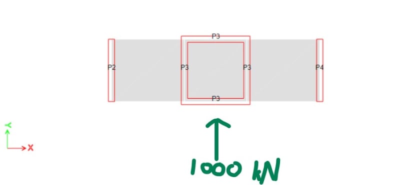
For the P2 and P4, the shear force distribution is fine because the below stories always have a greater value than the above stories (which is logical I assume).
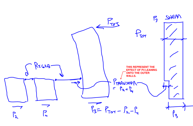
But for the P3, the bottom story has lesser value than the above story.
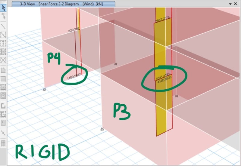
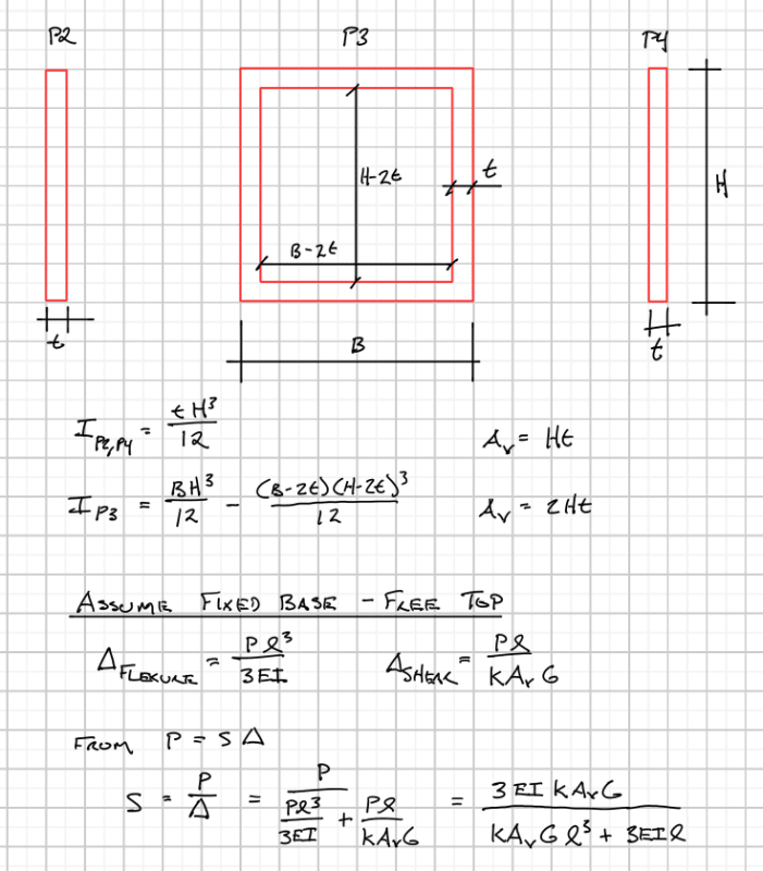
What makes the P3 wall has a special shear force distributon like that? Or is it because of the enclosed shape of the shear wall? Because if I delete the upper and bottom of P3 (so P3 become just 2 "I" shape wall), the shear force distribution becomes normal again like the other shear walls.
And by the way, if I change the slab/floor into "semi-rigid" diaphragm. Then the P3 problem is gone. All the shear walls have a normal shear force distribution.
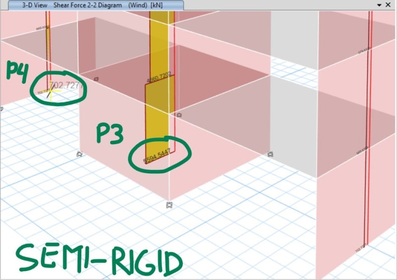
I would appreciate your thoughts about this matter. Thanks.


For the P2 and P4, the shear force distribution is fine because the below stories always have a greater value than the above stories (which is logical I assume).
But for the P3, the bottom story has lesser value than the above story.

What makes the P3 wall has a special shear force distributon like that? Or is it because of the enclosed shape of the shear wall? Because if I delete the upper and bottom of P3 (so P3 become just 2 "I" shape wall), the shear force distribution becomes normal again like the other shear walls.
And by the way, if I change the slab/floor into "semi-rigid" diaphragm. Then the P3 problem is gone. All the shear walls have a normal shear force distribution.

I would appreciate your thoughts about this matter. Thanks.

