Continue to Site

Eng-Tips is the largest engineering community on the Internet

Intelligent Work Forums for Engineering Professionals

  • Congratulations waross on being selected by the Eng-Tips community for having the most helpful posts in the forums last week. Way to Go!

Shear Force Distribution of Shear Wall 3

Status
Not open for further replies.

bulbamon

Structural
Sep 12, 2022
9
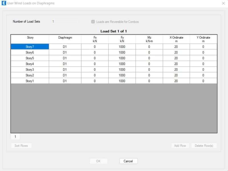
I have an example building consist of 7-story with 3 types of shear wall (P2, P3, and P4). I apply the same amount of lateral force each floor (1000 kN) using ETABS with rigid diaphragm floor. The slab/floor is defined as shell with automatic mesh. The lateral force ordinate is in the center of the building and the direction is to the Y direction.
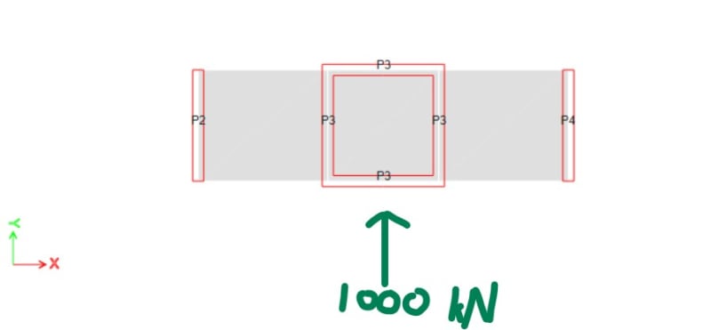
DENAH_EXAMPLE_yrhegu.jpg

Load_Pattern_WIND_qzzlpo.jpg


For the P2 and P4, the shear force distribution is fine because the below stories always have a greater value than the above stories (which is logical I assume).

But for the P3, the bottom story has lesser value than the above story.
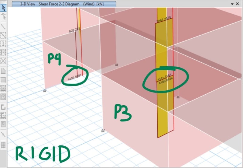
GAYA_DALAM_RIGID_cf2oec.jpg


What makes the P3 wall has a special shear force distributon like that? Or is it because of the enclosed shape of the shear wall? Because if I delete the upper and bottom of P3 (so P3 become just 2 "I" shape wall), the shear force distribution becomes normal again like the other shear walls.

And by the way, if I change the slab/floor into "semi-rigid" diaphragm. Then the P3 problem is gone. All the shear walls have a normal shear force distribution.
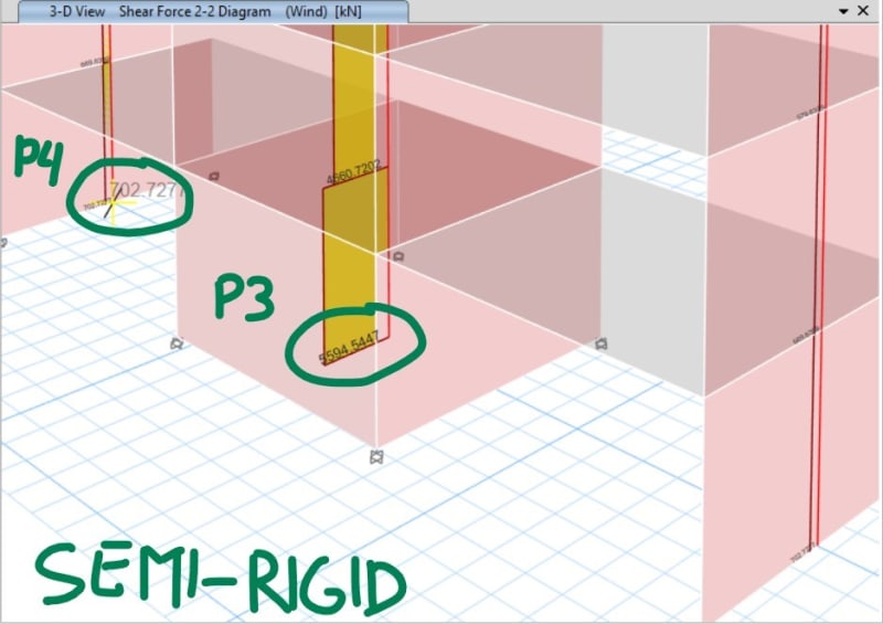
GAYA_DALAM_SEMI_RIGID_ujveyq.jpg


I would appreciate your thoughts about this matter. Thanks.
 
Replies continue below

Recommended for you

What do you get when you try to validate it by hand?
 
Interesting. I think that what you're seeing here is as follows:

1) Because your diaphragms are rigid, at any given level your model starts over from scratch with respect to shear distribution. All of the shear in the walls above gets absorbed by the diaphragm and then redistributed to the walls below based on their stiffness below alone. This is why the model yields more intuitive results when you switch to a semi-rigid diaphragm.

2) At any given level, the lateral stiffness's of the walls below are a function of:

a) The flexural stiffness of the walls and;

b) The shear stiffness of the walls.

3) As you move from the top of the building to the bottom of the building, flexural stiffness diminishes in importance while shear stiffness increases in importance. I believe that this is the reason for the migration of shear from the central core to the outer walls at the lower stories of the building.
 
Koot nailed it...one of the idiosyncrasies of idealizing the diaphragms as rigid.
 

I don’t understand.
Doesn’t that mean the proportion of shear to the core at the lowest level is not as much as what it is at levels above? Why does the cumulative shear reduce!
 
@phamENG

In this case (2 types of wall with different stiffness), I try to know what the program does that resulted this problem. I think if I try hand calculation the result will be normal (bottom story will always be greater than the top story).

@KootK

Thank you for your response and insight KootK. I don't quite understand the correlation of the shear stiffness that makes the outer walls receive more shear force.

If the shear stiffness is more "controlling" in the lower story, does that mean all the walls get the same effect (change of stiffness)? And if all the walls get the same effect, then does that mean that the middle/inner wall should always receive greater shear force too from top to bottom? (Like the outer walls that always receive greater shear force as we move to the bottom story).

@Dylan0022

Yes, that is what makes me confused. Because if we look at the shear wall that treated as the cantilever, the bottom story always has the maximum stiffness, therefore has the greatest shear force. Maybe @KootK can help us?

Thank you.
 
bulbamon said:
In this case (2 types of wall with different stiffness), I try to know what the program does that resulted this problem. I think if I try hand calculation the result will be normal (bottom story will always be greater than the top story).

That's my point. Until you do a verification by hand, you don't know how far off the program is. You've realized, intuitively, that it's wrong, but how do you expect to figure out what's wrong with it without having something to compare it to? Whether it's an error in the solver (unlikely - ETABS is pretty thoroughly vetted), an error in setting up boundary conditions, or some other issue with the way you put your model together, a comparison of correct results with the erroneous computer model results should point you toward your issue.

Due to the variations in stiffness of the walls, there's an offset between your center of rigidity and center of mass. If you ignore the stiffness of the diaphragm and simply take it as infinitely rigid, it exacerbates that difference. The offset results in an eccentricity and a torsional response from your LFRS. But the selected wall elements don't tell the whole story.
 
phamENG said:
Due to the variations in stiffness of the walls, there's an offset between your center of rigidity and center of mass.

I don't see it. The wall stiffnesses do indeed vary but do so in a way that symmetry is maintained. If there's a torsional thing going on, I'm guessing that it would be the result of an automated ETABS seismic load consideration or something. And I doubt that's the case given that OP seems to have set this up as a deliberate validation exercise. Perhaps OP can confirm whether or not his model is producing torsional behavior.
 
Dylan0022 said:
Doesn’t that mean the proportion of shear to the core at the lowest level is not as much as what it is at levels above?

Yes, and that's just what we see here.

Dylan002 said:
Why does the cumulative shear reduce!

bulbamon said:
Because if we look at the shear wall that treated as the cantilever, the bottom story always has the maximum stiffness, therefore has the greatest shear force. Maybe @KootK can help us?

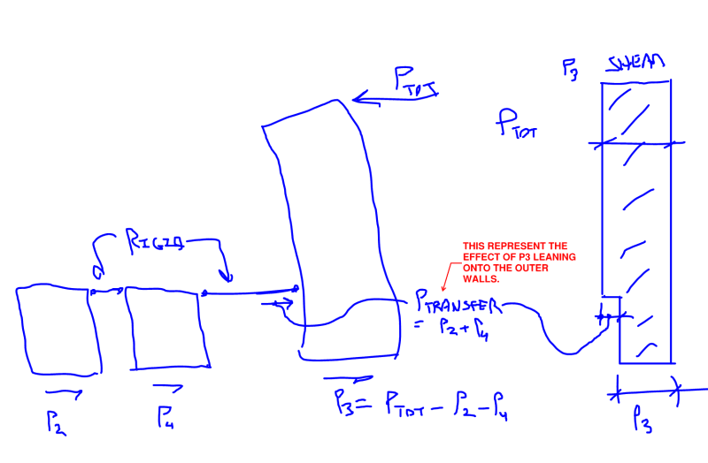
It may be useful to visualize this as a partial incarnation of the classic backstay effect described nicely in this article: Link. In this case, the backstay effect is nowhere near enough to reverse the sign of the story shear in P3 but it is enough to account for the draw down at the base level.

I've tried to illustrate this concept in the modified version of your setup shown below. Any chance that helps?

c01_uogmfm.png
 

Thank you very much. That makes sense.
Does that mean a semi-rigid diaphragm is better and realistic?
 
The difference is in the name. Semi-rigid diaphragms are able to displace somewhat based on the material properties of the diaphragm. I will let koot sketch it out :"D

Rigid is never really the realistic case, nor flexible. So I would agree that semi-rigid CAN be more realistic. Big emphasis on the can here because it must be modeled appropriately to give realistic results.

The rigid diaphragm is modeled as an infinitely rigid body, it doesn't exist in reality. Like others have said as you go down the building each diaphragm level takes all the loads from above then distributes them horizontally based on the stiffness/distribution of the walls and columns below. This allows the force to flow in and out of the walls and columns at each rigid diaphragm level.

For what its worth, most of the people I have worked with are not comfortable designing the walls below for less shear than the walls above, we would carry at least the higher force down to the lower level and design based on that. Also important to consider how the overturning is transferred. Rigid diaphragms can be modeled to distribute out bending moments from the bottom of the walls/columns as well. In reality those loads are going to flow mostly straight down.

Nearly everytime I have used rigid diaphragm analysis I have had to wrestle with these ideas, and go back and make some hand verifications etc in order to feel good about the design.
 
@driftLimiter
Do you know how programs like ETABS deal with rigd, semi-rigid and flexible diaphragm behind the scene?

Can you please give an example?
 
Rigid Diaphragm can be a restrained stiffness matrix analysis similar to this: Link. ETABS is likely generating a master node at the center of gravity and doing rigid links between the master node and all other nodes in the more general sense this can be more involved than the linked method.

Semi-Rigid is full finite element analysis utilizing shell elements

Flexible can sometimes be a simple tributary model utilizing vector distances between lateral resisting elements
 
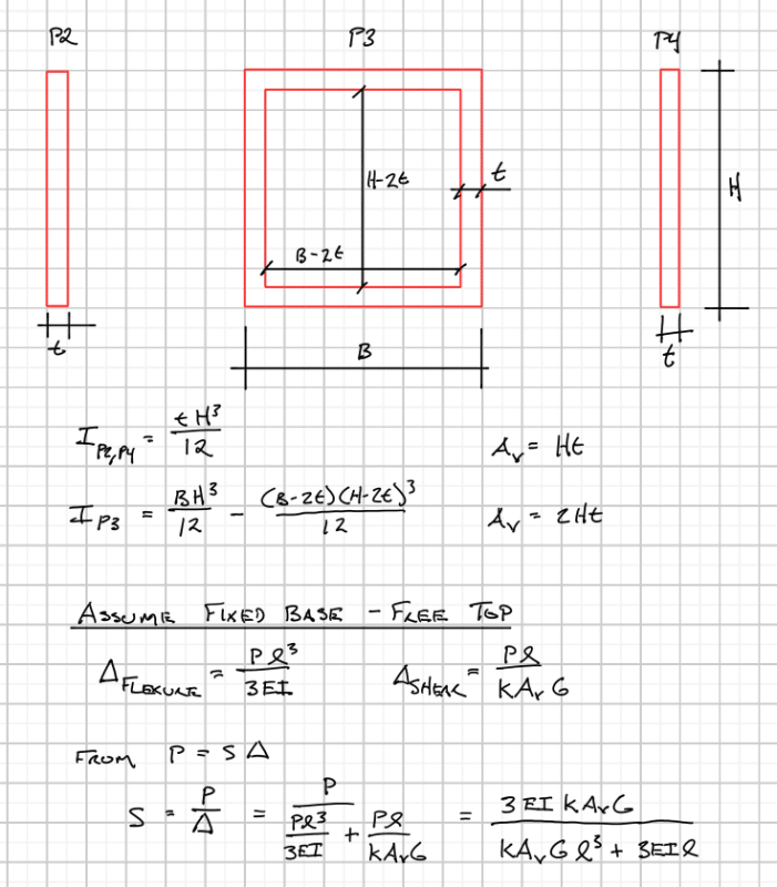
Instead of just shear "walls", you have a shear/flexural tube in the middle. The tube stiffness is much greater than the walls alone. Celt's calcs are a little small for me to read, but I think that's what he's showing you. The higher up the building, the more flexural stiffness comes into play. Kind of a neat example, really. Informative.
 
Pardon me if I am long-winded here.

Each technique is a means to determine the horizontal distribution of reactions at a given diaphragm level.

Rigid is basically the easiest to model mathematically. Link
Each floor can be modeled as a series of three springs, one for each lateral direction, and a torsional spring. These springs are generated by summing up the stiffness of lateral elements first in each direction, then using a polar moment of inertia to derive the spring constant for the torsional spring. Part of this process is determining the so called 'center of rigidity' this is the location on where applied shear loads in either direction do not cause rotation of the slab. For seismic loading, the center of mass is also located, and any offset between the center of mass and the center of rigidity will cause an inherent torsional response. The code requires to consider the inherent torsion, plus an additional percentage of eccentricity due to 'accidental eccentricity' this is to account for unknowns when determining the center of mass. The overarching principle to consider is that the displacement of the rigid displacement of the slab must be 100% compatible with the displacement of the shear walls and columns. In other words, if the slab deflections 12" in the X-direction, then every wall/column attached to it must also deflect 12". There is no differential movement of the slab between lateral elements. Rotation of the slab complicates this a bit but its as simple as calculating the deflections due to direct shear, then combining it with deflections due to rotation.

The beauty of modeling a rigid diaphragm is that the slab itself is a constraint not an element. This means you don't physically need elements to represent the slab, you don't need to worry about mesh of it etc (at least in terms of the horizontal distribution of forces). There are some downsides and oddities, some of which have been discussed here.

Flexible diaphragm is very much the opposite of rigid, the diaphragm offers zero relative stiffness between lateral elements. This method treats each diaphragm region between lines of lateral resistance as a simply supported beam. The reactions at the ends of the beams flow into the shearwalls based on statics of a simple beam. Since the diaphragm is modeled with zero stiffness, once the loads are into the walls, they cannot come out and go anywhere else (like your Original Post). This is a very common approach for wind and seismic in light frame construction, as well as metal deck roofs. My understanding is that computer programs essentially follow the same procedure that one would follow by hand, calculate the tributary width to a lateral line, determine the reaction based on statics of a simple beam.

Again as with rigid diaphragms, no actual FEA elements are needed to determine the horizontal distribution of forces.

Now finally the beast in the room. Semi-rigid diaphragms.
Semi-rigid is a loose way to refer to diaphragms modeled with their actual in-plane stiffness. In order to achieve this, FEA elements must be modeled and given proper material and section properties. They become part of the overall FEA model and are included in the global stiffness matrix. The loading is applied directly to the diaphragm elements themselves, and the results of the FEA give rise to the loading into the shearwalls/columns.

The difficulty here is mostly wrapped up in setting the material and section properties correctly. Depending on what design check your interested in, you may want more or less 'accurate' stiffness of the diaphragm to modeled. We had a good discussion about this recently that might help feed your mind on Semi-rigid a bit more. [URL unfurl="true"]https://www.eng-tips.com/viewthread.cfm?qid=499735[/url]

The semi rigid diaphragm may transfer loads around at floor levels like your original post, but compared to a rigid analysis the effects should be less pronounced.

On the design side of things, semi-rigid and rigid approaches generally take a bit more effort to determine things like diaphragm shear, drag-strut collectors, etc. With the flexible approach, the diaphragm shears and DSC forces are very easy to determine.
 
Hello everyone. Sorry for the late respond. Thank you for all the explanation and discussion in these past 2 days from phamENG, KootK, Dylan0022, driftLimiter, Celt83, and JLNJ.

@phamENG

Yes I understand and I will look into that too, thank you for your explanation.

@KootK

The center of mass and the load location are the same, so it should not producing torsional behaviour.
The center of rigidity I assume is the same too because the structure plan is very simple.
And thank you for the sketch and explanation about backstay effect.
I think if backstay effect happens, the effect would have come since the above story (because I have a typical plan and the walls are continous in all story). Or maybe I'm missing the point?

@Celt83

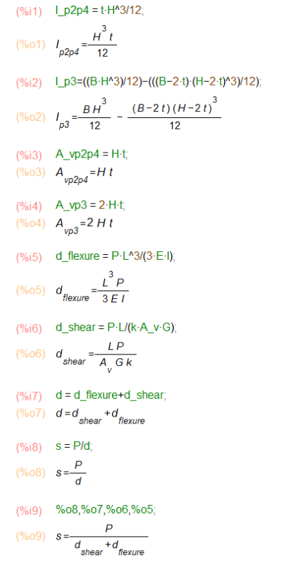
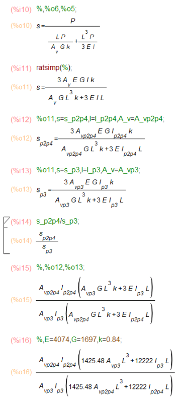
Thank you so much for your written hand calculation, very helpful.
I have a question regarding that. When you calculate the stiffness of the wall in the 1st story and 7th story, I notice that the stiffness equation becomes a function of height. Does that mean the stiffness changes as we move to another story? And connecting them to the cantilever analogy, does that mean a simple cantilever beam also has a change of stiffness along the length?
I was wondering that concept because for the flexural stiffness I see that you use "PL^3/3EI" with "L" is the height of the story.

@JLNJ

Yes the "tube" shape wall has very high flexural stiffness compared to the "I" shape walls. But I don't quiet get it why the "tube" shape wall in the bottom story loses its high flexural stiffness compared to the above story. The overall stiffness still increases in the bottom story, but in the same time the "I" shape walls increase their stiffness higher (?).
 
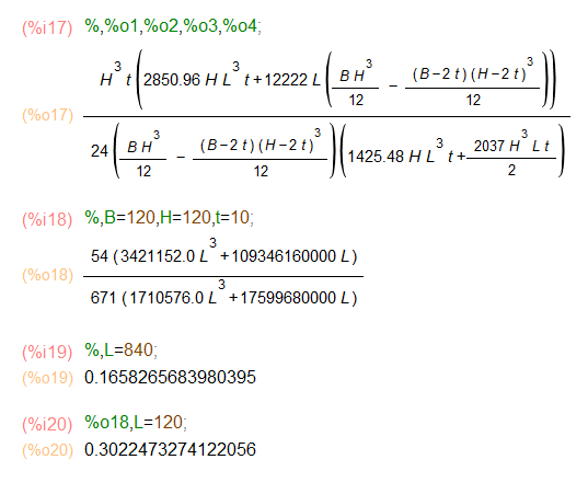
The previous calculation is a little off here is a better one that remains consistent with P3 being one entity and P2,P4 being two entities. To answer your question though yes the stiffness varies with the length (story height)

Screenshot_2022-11-11_154237_ujzohg.png

Screenshot_2022-11-11_154313_ibfydk.png

Screenshot_2022-11-11_154333_abztws.png

Screenshot_2022-11-11_154401_vsvus5.png

At story 7 you can see the relative stiffness of 0.16582 is nearly equivalent to the ratio of the moment of inertias which works out to 0.16095

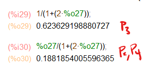
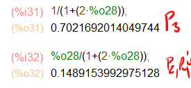
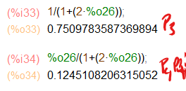
Here are the load distribution Factors for a directly applied load:
At story 1:
Screenshot_2022-11-11_155607_oanqo6.png

At story 2:
Screenshot_2022-11-11_155925_t7eck1.png

at story 7:
Screenshot_2022-11-11_155948_rxtzzp.png
 
Status
Not open for further replies.

Part and Inventory Search

Sponsor