the Paper Owl
Structural
Good Morning everyone,
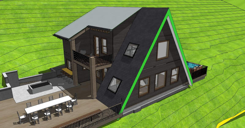
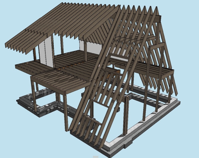
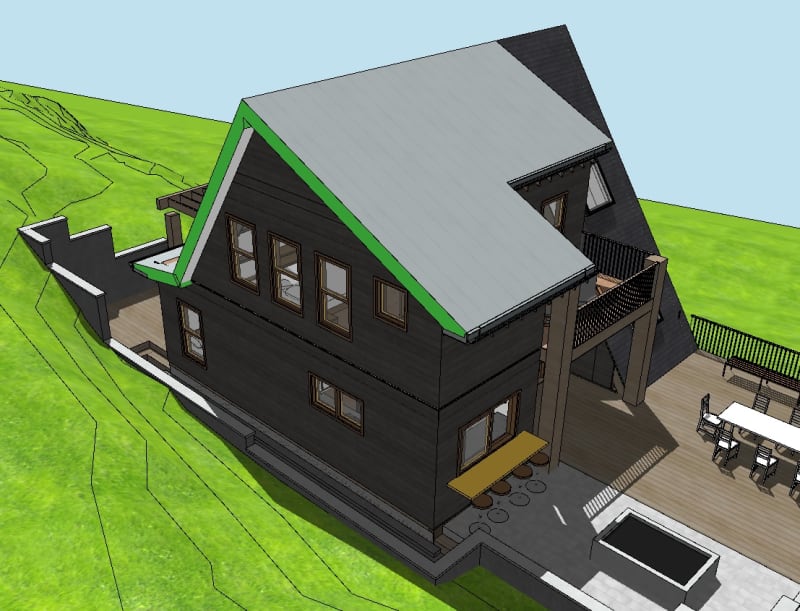
I am in the process of the shear design for an A-Frame residential unit and am wanting to model the shear response of the structure properly. At one end of the unit (Elevation A), the gable end wall is balloon framed and is not connected to the second floor platform (as it is the area where the stairwell is accessed and showcases the hot-roof volume ceiling). My questions are as follows:
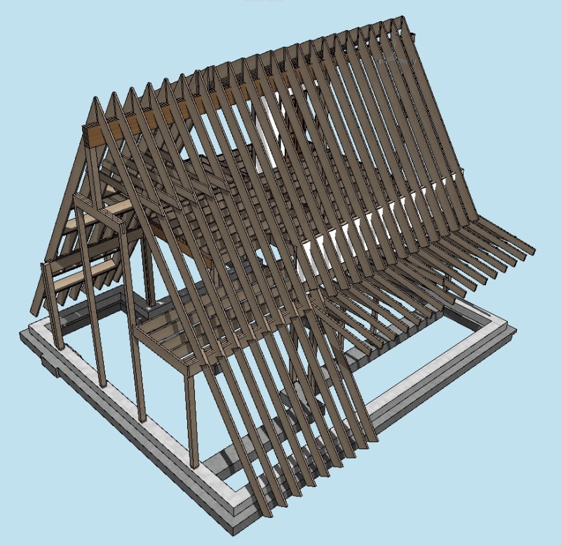
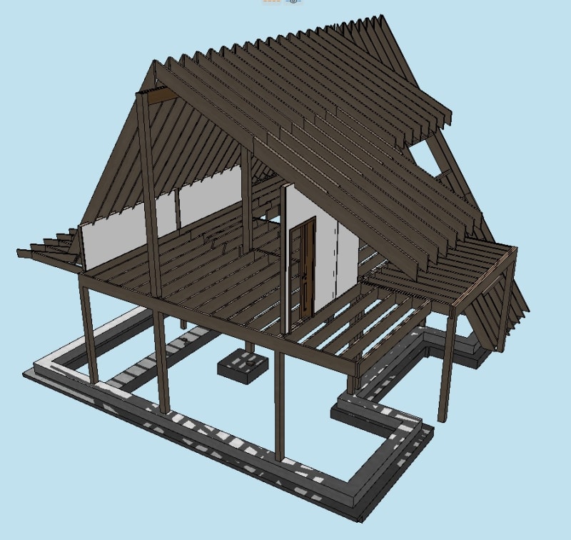
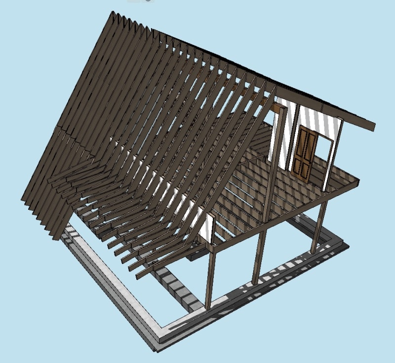
1. When modeling the response of the structure from the lateral wind on Elevation A, there is no floor diaphragm to cause racking. There are however the two perpendicular roof diaphragms (each terminating at the first floor sill plate). This wall will be fully designed for a deflection failure state in which it will follow suit with the qualms of the dreaded window gable end wall but I am however unclear if each roof diaphragm (18:12 slope - 2x12 rafters, blocked) will essentially act in the same regards as a floor diaphragm and cause point loads at the locations that are resisted by the diaphragm (the top of each perpendicular dropped beam where the rafters are lapped and spliced). I have been assuming this as the case, and designing the connection at each dropped beam to withstand the shear induced by each point load as well as the desire for the beam to withstand being pushed out of plane (shear transfer at the PSL column supporting it and PSL column bracing for the bending that would be caused).
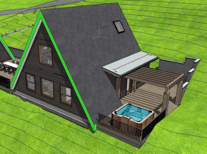
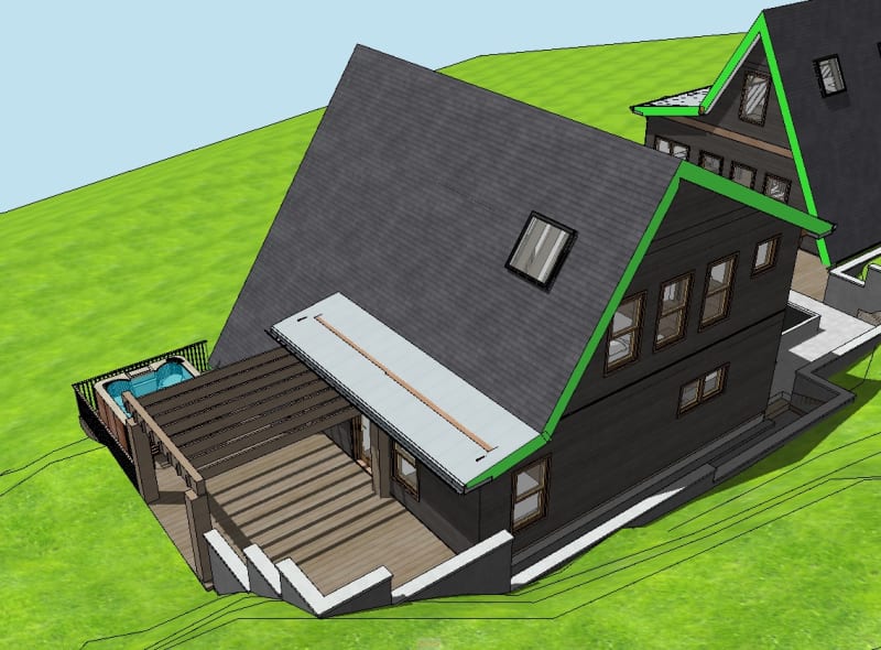
2. Elevation B has a second floor platform intersecting the "gable / salt box" end wall, but has a large volume / cathedral ceiling. My preliminary design is using the area for the lateral wind load - with a lower boundary line at the midpoint of the first floor wall, extending to the entire ridge of the second floor. This is assuming that given a strong wind event, each cathedral roof diaphragm, along with one perpendicular wall will "be along for the ride" and place a lateral point load at the connection of my top plate (at the second story platform). My design follows ( B ) on the sketch. See sketch for the visualization.
Thank you in advance.
I am in the process of the shear design for an A-Frame residential unit and am wanting to model the shear response of the structure properly. At one end of the unit (Elevation A), the gable end wall is balloon framed and is not connected to the second floor platform (as it is the area where the stairwell is accessed and showcases the hot-roof volume ceiling). My questions are as follows:
1. When modeling the response of the structure from the lateral wind on Elevation A, there is no floor diaphragm to cause racking. There are however the two perpendicular roof diaphragms (each terminating at the first floor sill plate). This wall will be fully designed for a deflection failure state in which it will follow suit with the qualms of the dreaded window gable end wall but I am however unclear if each roof diaphragm (18:12 slope - 2x12 rafters, blocked) will essentially act in the same regards as a floor diaphragm and cause point loads at the locations that are resisted by the diaphragm (the top of each perpendicular dropped beam where the rafters are lapped and spliced). I have been assuming this as the case, and designing the connection at each dropped beam to withstand the shear induced by each point load as well as the desire for the beam to withstand being pushed out of plane (shear transfer at the PSL column supporting it and PSL column bracing for the bending that would be caused).
2. Elevation B has a second floor platform intersecting the "gable / salt box" end wall, but has a large volume / cathedral ceiling. My preliminary design is using the area for the lateral wind load - with a lower boundary line at the midpoint of the first floor wall, extending to the entire ridge of the second floor. This is assuming that given a strong wind event, each cathedral roof diaphragm, along with one perpendicular wall will "be along for the ride" and place a lateral point load at the connection of my top plate (at the second story platform). My design follows ( B ) on the sketch. See sketch for the visualization.
Thank you in advance.
") ). I have to say that this home (and its little brother being built next door) have been great teaching projects where I find my time split during the day either reading / researching and detailing.
). I have to say that this home (and its little brother being built next door) have been great teaching projects where I find my time split during the day either reading / researching and detailing.