Eng-Tips is the largest engineering community on the Internet

Intelligent Work Forums for Engineering Professionals

Shear Pin Design 1

Status
Not open for further replies.

Otibix 1996

Mechanical
Feb 2, 2024
4
0
0
GB
FBD_avfkii.png
Hello,

I'm facing a problem trying to assess a shear pin design. The design is made by a third party so we have limited influence but have been asked to ensure the design is fit for purpose.

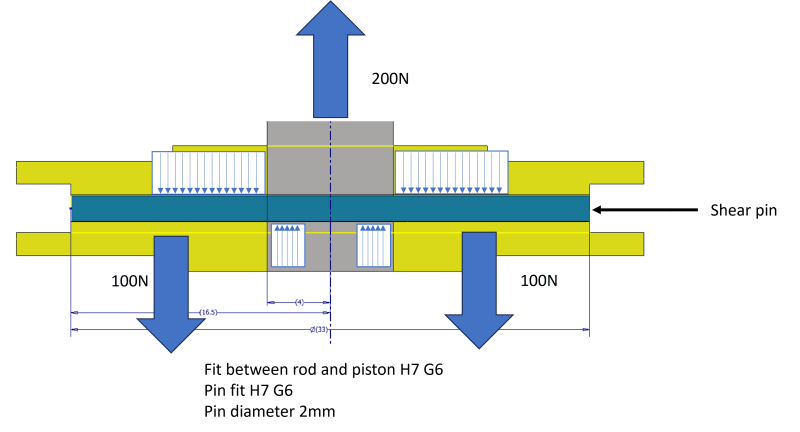
The design is for a circa - 2mm pin which attaches a 33mm OD pneumatic piston to a 8mm OD piston rod. The pin must be capable of withstanding a design force of 200N but must shear at 500N applied to the piston rod.

The pin was sized accounting for only the shear force and I have been asked to account of bending and bearing stresses in the pin, but seeing as the pin is 33mm long (width of the piston) I am struggling to determine an appropriate moment.

We are working to EN13001-3-1 but this greatly overestimates the force based on the pistons width.

Is there any advice on how to consider this?

FBD
 
Replies continue below

Recommended for you

Hi Otis Dickson

Am I reading your post correctly the -0.05mm between the rod and the piston suggests an interference fit if that is the case the shear pin won’t see any load until the interference fit becomes a clearance fit? Or am I reading the diagram wrongly.

“Do not worry about your problems with mathematics, I assure you mine are far greater.” Albert Einstein
 
As I recall, the double shear tests are run with <.010" gap between piston and mating part. If you abide by that then you can use the double shear numbers that are published by the manufacturer. Doesn't help in making an FBD though.
 
Desert Fox - Good spot - The drawing i was given wasn't finished. The actual fits both appear to be G6H7.

For my initial draft i took account of this and suggested that it would be a case of pure shear. I was asked to account for localized deformations close to the edge interface.

 
In tight fits there is little local deformation that it has no material impact on the shear value.
This is sure a small pin.
How repeatable are the shear values?
I presume that you have tested these?

= = = = = = = = = = = = = = = = = = = =
P.E. Metallurgy, consulting work welcomed
 
Thanks for the input Ed.

We are waiting on these to be tested. Essentially, the piston actuates a swing arm, we need the system to fail when applying a load to lift the unit out of a restricted hole without overloading the hoist. the manuf wants to use a weld rod alloy which as you can guess there isnt much data for. We are trying to identify an alternative wire alloy and diametric size that would be suitable.
 
making sure that something fails at a prescribed load ... that's tricky. How do you ensure that your delivered machine does have a pin that 150% the strength of the pin you tested ? Spec properties are at the low end of the population (95th to 99th %-ile).

is this a 1-off or production run ? you could test each piece of wire.

"welding rod" material ... geeze !??

one way to make it fail would be to two pieces of wire, butted together on the CL ... so that in a overload the wire would shear locally, or maybe pulled our of the female lugs. But how would this hold up under day-to-day loads ? There are ways to trap the wire so it doesn't migrate out of the hole.

"Hoffen wir mal, dass alles gut geht !"
General Paulus, Nov 1942, outside Stalingrad after the launch of Operation Uranus.
 
The strength for these will need to be in a very narrow range in order to control the shear.
We used to use to make shear pins and we cut "U" groves in the shear zones.
For each heat lot we tested samples and adjusted the depth of the grooves to control the shear load.
They are going to have to buy real wire with tightly controlled tensile properties and tight OD tolerances.


= = = = = = = = = = = = = = = = = = = =
P.E. Metallurgy, consulting work welcomed
 
Its a one off production. I think the plan will be to test and substantiate based on material strengths and to demonstrate on a sample system that the whole shear assembly works.

I've been pointed in the direction of the Air force method for assessing the bending stress. Essentially determining the point where the pin bending stress is equal to the bearing stresses on the piston and the rod.

If you have any experience or thoughts on this method please let me know?

I appreciate the feedback, I'll feed some suggestions up the chain!
 
yes, we generally analyze these pins for bending; generally starting with a uniformly distributed load. With large thicknesses this produces (as you've seen) highly conservative moments. Then we think ... as the part begins to fail the load "drifts" towards the shear plane. So we reduce the moment by ...
1) consider only a portion of the lug (near the shear plane) to be effective. You might start with 1/2 the thickness, maybe 1/2 the thickness of the thinner lug
2) a triangular distribution is often used (base either the thickness, 1/2 the thickness, 1/2 thickness of the thinner lug)
3) ultimately the pin fails in shear at the shear plan (so no bending !?)

"Hoffen wir mal, dass alles gut geht !"
General Paulus, Nov 1942, outside Stalingrad after the launch of Operation Uranus.
 
Hi OtibiX

I cannot see why you can’t just use simple beam Theory and assume a simple supported beam, at a depth of 2mm to a length of 33mm gives an L/D ratio of 16.5:1. However I think the shear pin is to flimsy and will bend a lot before failure, not to mention possible work hardening of the pins during both manufacture and during normal operation. Also the maximum bending stress which will be at the beam centre will have the minimum shear stress at that point.

“Do not worry about your problems with mathematics, I assure you mine are far greater.” Albert Einstein
 
A U-shaped groove is really required to have a controlled shear failure. Otherwise, the radius of the edges of the holes will be a significant factor, as well as their hardness. The sear pin hardness should be lower than the material the holes are made from. Aluminum pin, for example.
 

concur...important... to help provide a uniform shear failure capacity. Without the 'U grooves' the failure data can/will have a much bigger scatter.

-----*****-----
So strange to see the singularity approaching while the entire planet is rapidly turning into a hellscape. -John Coates

-Dik
 
Not only does the pin need to be softer than the blocks, but you need to make sure that even after shear and strain hardening that there is still a good gap in the hardness.
But pins that are too soft may suffer damage from handling, installation, or just repetitive loading.
It helps to make the pins from an alloy that doesn't strain harden much. (don't use SS)
Though people often avoid using mild steels because of long term corrosion concerns.
A bit of synthetic oil should be used when these are installed to minimize binding.

= = = = = = = = = = = = = = = = = = = =
P.E. Metallurgy, consulting work welcomed
 
I disagree with the groove idea. Yes, it's we do for carefully designed pins, to fail at a controlled load. But this pin is
1) only 2mm diameter, and
2) welding rod material.

The ask is to be fine at 10ksi shear, and to fail at about 25ksi (you use your units, I'll use mine !). This is just a P/A calc ... I suspect the loading (sharp edge ?) may have some impact. Looking for a material with a 20-25ksi (140-170 MPa) Fsu.

"Hoffen wir mal, dass alles gut geht !"
General Paulus, Nov 1942, outside Stalingrad after the launch of Operation Uranus.
 
There are breakaway couplings on the market. An adjustable ball-detent could be dialed in to a fairly precise load. Also, might consider a magnetic breakaway. A sheared pin indicates you are not requiring anything to be automatically resettable.
 
2mm is a ridiculously small pin to try to make it a fuse pin (defined failure load).
The only practical way to deal with this is to procure a number of pins of the same lot of material, test a number of them in a test fixture representative of the actual parts, and determine the as tested strength range. If not within the required range and too high, then machine small grooves at the shear plane and repeat. If strength too low then get a better material or make diameter larger.
Forget trying to predict shear strength with FEA.
 
Some small engines ( lawnmower, etc) use aluminum keys for the large magneto/flywheel.
I think the are die cast.
They only fail under extreme conditions like "mowing" an embedded concrete post and the blade stops NOW.

Doesn't mess up the keyways in the steel crank and flywheel hub too much.
 
Status
Not open for further replies.
Back
Top