Continue to Site

Eng-Tips is the largest engineering community on the Internet

Intelligent Work Forums for Engineering Professionals

  • Congratulations The Obturator on being selected by the Eng-Tips community for having the most helpful posts in the forums last week. Way to Go!

Shell and tube HE tube rupture scenario

Status
Not open for further replies.

LuNL

Petroleum
Jun 29, 2015
12
Dear Engineers

I have encountered a scenario study for tube rupture inside the shell and tube heat exchanger.

tube side : LNG 8 barg, -157 C in, and 25 C gaseous out
shell side: water/glycol, 2.5 barg, 55 C in and 35 out.

I assume the possible rupture will be on the back side of the tube sheet, so my question is : how big the rupture crack, hole can be ? (better to have a reference, in case of somebody may question me)

Since I need to determine the rupture disk's required flow rate, which is protecting the low pressure side.

Thanks
 
Replies continue below

Recommended for you

Hi Emmanuel

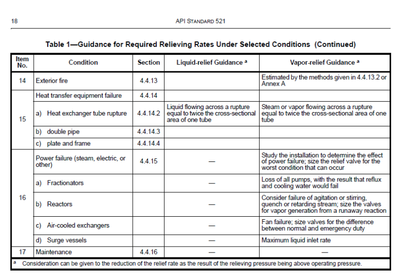
Thanks for this. And which revision of API 521 do you have? The one I have is only a table with text, and in paragraph 5.19 there is nothing related to number or size calculation.
I don't have that Crane TP 420, so could you specify a bit detail where this "twice the cross-sectional area" comes ?

 
It is the 6th edition (latest). See attached snapshot of the table 1, item 15a.
Untitled_qn4ao4.png


Dejan IVANOVIC
Process Engineer, MSChE
 
Mine is fifth, time to go shopping for a new one, thanks a lot !
 
A complete shear of one tube is possible, and this is a typical type failure due to hi cycle fatigue from vibration. This leads to the scenario of 2 flow areas. The "casualty" flow from the hi pressure system to the low pressure system may be acoustically choked, maybe not- to be calculated for both flowpaths.

"Nobody expects the Spanish Inquisition!"
 
Hi davefitz

I understand this.
Just curious, can I also apply the API sizing equations for determining the flow through a rupture hole or creep/crack ?

I did a simple check between API PSV sizing equation and nozzle injection flow equation Q=uA rqrt (2*deltaP*rho), u = 0.6 for liquid flow. the answers from both methods only have a difference about 2%

 
I would say that's it - you have a flashing liquid flow from 8 barg to 2.5 barg so there are no unknowns. If you are interested to find out how fast the pressurization of the shell occurs, you can try build and run a dynamic simulation model of the system. See

Dejan IVANOVIC
Process Engineer, MSChE
 
Is this RD planned to be located directly on the shellside of this LNG vaporiser ?

What is the freeze temp for this glycol / water mix - is it not much higher than -157degC? If so, if you develop a pinhole leak on a tube, solids will grow on the LP shellside during a shutdown and the RD inlet could get blocked ??

Better to have the entire HX to be specified with design pressure of LNG side, add a TSLL on the shellside to trip the LNG feed (in case of low MEG flow), and install the RD or PSV on the expansion drum side of the closed loop MEG / water loop.
 
Ideally, an FD / ID air cooler for this LNG vaporiser would be much safer (or some fluid in a closed loop with no risk of freezing at -160degC in a shell and tube HX).
 
Hi georgeverghese

Yes, we have the TSLL on the LP side, which can control the automated valve to close the LNG flow to the tube, therefore only small amount of LNG is trapped in the tube, while the Water/Glycol is recirculating, so frozen is protected.

But personally concerned, I will put the RD horizontally, so the percussive shock wave in water will open the RD immediately, better than having air under the RD , as a buffering , is it better ?

 
Relatively speaking, yes, that maybe better. But it still does not address the case where there is a failure of the TSLL; and the RD must not be compromised even in that case. This is what may be asked during a hazop of this unit.
 
Also look at the scenario of glycol circuit failure (no flow condition). The fact that TSLL will stop the flow of LNG does not necessarily prevent from freezing of the entire shell, because the LNG trapped in the tubes could ultimately cause freezing of glycol inside the shell, if no other actions are taken. You can easily check if this will happen by comparing m*dH for LNG in vaporization vs. m*Cp*dT for glycol, and calculate the final glycol temperature. Mass of both fluids inside the exchanger is known. Localized freezing seems very likely.

Dejan IVANOVIC
Process Engineer, MSChE
 
Yes, which means that it is likely that every time the HX stops operation, the shellside will freeze up even with LNG inlet flow stopped, assuming that MEG flow is stopped.

The other thing that needs to be checked from a heat transfer point of view is that the tube OD skin temp must be maintained at several degC higher than freeze point of MEG - water, for the design case duty, else solids will build up on the tube skin OD , and the HX will fail on thermal duty.
 
Hi guys,

I did the calculation and suppose the LNG is leaking at a constant speed, it will freeze the shell side, sure.

But there is only few LNG trapped in the tube, and the automatic valve will stop coming LNG in 5 sec. Even though, the LNG in the tube remains only in the beginning , which close to the tube inlet, then it should be vapor after half way travelling through the tube bundles .

If everything is calculated in rate, seems very big, but considering the total tube volume is 37L, and 1/4 is LNG, (but I can have a vaporization speed round to 6000L/min) how should I deal with the high rate?
 
In a typical S/T HX, there will be "dead zones" on the shellside nearest to the cross baffles - the local shellside velocuty may be much lower than the "average" shellside velocity. So the tube OD skin temp will be the lowest at these dead zones.
 
Actually I just talked with the HE supplier, they told me freezing is okay for my operating condition since the shell side can handle -50 and 10 barg MAWP, so rupture on the tubes should not be a big problem.

This makes me think

Suppose we have a heating fluid that never freezes, and LNG keeps leaking to the shell side and being vaporized into gas. The turbulent vaporization will be so dreadful that I got a required discharge flow rate of that heating fluid equals 1480.1 m3/h (since the rupture disk is on the outlet pipe, instead of the shell side). This lead to a 6 inch diameter disk that we only have a 2 inch pipe. If I have a result like this, it shows there is something wrong with the design and maybe I should re-consider the location of the disk, like on top of the HE shell side.

Is this thinking correct ?

Thanks !
 
At the relatively low pressures involved, consider bumping the design pressure of the shell to match the tubeside pressure (or 10/13 of the tubeside pressure per API). If the exchanger is not a very large diameter, then the incremental cost may not be significant (maybe less than the engineering time for a dynamic study).

The RD can then be installed on the connected piping if still necessary.
 
Status
Not open for further replies.

Part and Inventory Search

Sponsor