Continue to Site

Eng-Tips is the largest engineering community on the Internet

Intelligent Work Forums for Engineering Professionals

  • Congratulations KootK on being selected by the Eng-Tips community for having the most helpful posts in the forums last week. Way to Go!

Shell Elements as Slabs 2

Status
Not open for further replies.

CrabbyT

Structural
Feb 12, 2019
165
In your structural models, what do you think about using shell elements to represent concrete floor/roof slabs?

I've been hesitant to do this because the effects seem drastic. For comparison, I made two duplicate models. One uses area loads to represent a roof deck, the other uses shells. I took care to make sure the loads and pressures were equivalent between the two models.

For the roof purlins, using shells vs. area loads results in stress ratios of 0.49 and 0.75 respectively.

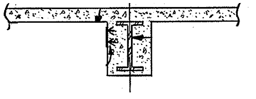
The building I'm dealing with is a steel structure encased in concrete. The beams were wrapped with wire mesh when the building was constructed in the 40's. Based on the AISC Steel Manual from 1947, I believe this was treated as a composite system.

Anyway... thoughts? I've always had some concern that shell elements could add unrealistic amounts of rigidity to the stiffness matrix, but I don't know if my concern is valid. It's more conservative (for the steel, anyway) to exclude any contribution from the slab. But is it unrealistic to include it?

CrabbyT
 
Replies continue below

Recommended for you

CrabbyT said:
The building I'm dealing with is a steel structure encased in concrete. The beams were wrapped with wire mesh when the building was constructed in the 40's. Based on the AISC Steel Manual from 1947, I believe this was treated as a composite system.

Really!? That sounds like an unusual construction technique. I'm not a building guy though, so perhaps it's more common from that era than I think.

Based on your description, you have a concrete encased steel beam (or purlin) composite with a concrete deck? Can you post any pictures of this as-built condition so we can see?

If you are modeling it with area loads vs shells then I can absolutely see why the demand would be higher for the former case. Does your FEA program allow you to take a summation of the forces for the composite section (purlin plus trib. width of deck) or are you just outputting the forces for the purlin (line element) by itself? The later would not be the correct approach for a composite system.
 
Shells do work fine, but you have to be consistent in you assumptions. Right now, you are modeling two completely different (but both equally constructable) structures.

When you use area loads, you are implying that the shell does not carry any load at all. (All loads are carried by the purlins). You put the purlins, and then the slab goes on top and rests over the purlins.

When you use shells as-is, you are implying that (a) both the purlins and the shell will act compositely. This includes making sure that shear studs were placed as required in order to achieve the "compositeness" you are using in the model. Unless you are doing a staged construction model, you are also implying that (b) that the purlin and the slab were only loaded when they were acting as a composite unit (ie. the purlin were shored until the slab had been cast).

Most (all?) structural software allow you to assign property modifiers to the slab. I recommend you to experiment how the different parameters affect the behavior of the model.

A few things to note:
[ul]
[li]For slabs, the moment of inertia is generally not the gross moment of inertia. As a rule of thumb, ACI 318M-19 6.6.3.1.1 states that the moment of inertia of the shell is aproximately 0.25 I[sub]g[/sub][/li]
[li]Make sure that your meshing level is fine enough for your purpose[/li]
[li]When designing/checking the slab, you can't ignore the torsional component (M[sub]xy[/sub], M[sub]12[/sub], etc). The easiest way to deal with it (thought certainly not the most "technically correct") is to do a torsion-free analysis by using a property modifier to set the torsional stiffness of the shell to a really low value. (ACI 447R-18 4.5)[/li]
[/ul]

Until you've learnt all the ins and outs of whichever software package you're using, I recommend you to verify the results with hand calculations; you should get about the same answer regardless of the method provided that the same assumptions (construction staging, compositeness, etc) are kept.

Edit: I'm not sure I would consider a beam wrapped in wire mesh as "composite". There´s no real positive connection (shear studs) between the steel member and the concrete.
 
Good replies so far, thanks!

Forgot to mention, I'm using RAM Elements. I can edit the thickness of the slab, the material, and the concrete cover.

Additionally, for the time being, I'm not worried about checking the slab. I'm analyzing the existing steel structure to determine if it is capable of supporting new equipment in addition to the existing loads.

STrctPono - The beams were cast into the concrete and are integral with the floor slabs. The slab does not sit on top of the purlins (or floor beams). I've attached a picture.

mchen - It's interesting, but the 5th edition of the 1947 AISC Steel Manual didn't require shear studs. Among other requirements, it requires that composite action shall apply if "the concrete haunch has adequate mesh, or other reinforcing steel, throughout its whole depth and across its soffit." If you're an AISC member, historic manuals are available at
For steel decks, I can absolutely see why shear studs would be required by current codes. For cast-in-place decks that were formed with plywood and shored until hardened, I could believe that mesh would adequately bond the steel beam to the concrete.

I'd love to verify some of this with hand calcs. However, I've looked extensively for an example, and I've came up empty handed. The AISC has a guide for concrete encased W-shape columns, but I'm not worried about the columns just yet. While studying for the PE, I remember doing a practice problem involving composite strength of a wood beam sandwiched with plates. I imagine this would be similar. Do you happen to have a resource you could share for determining the composite strength of a concrete encased beam?

Regarding the torsion free analysis, are you recommending that I modify the torsional constant for the purposes of checking the steel?

Conc_Beam_liaued.png
 
I wonder why you have chosen shell element instead of plate element. The concrete slab usually wouldn't so flexible thus the in plane stresses are dominant.
 
In your structural models, what do you think about using shell elements to represent concrete floor/roof slabs?

Never done it. Don't see the reason for it. (If we are talking a normal, flat slab.)

In fact, even when I've had a curved body to represent.....I've still used (finely meshed) plate elements. (Quads for the most part.) And have gotten good results.

 
Huh, didn't realize there was a difference between plates and shells. RAM refers to plates as shell elements.

Just curious, what are you guys talking about with regard to shell elements? Does your software differentiate between the two?
 
The linked blog does not provide complete description of each element typically used in FE analysis, but as you are a RAM user, it might be just enough for you to get some idea from the developer. Link
 
The FEA program that we use in my office don't even bother with plate elements. They use an element that they call a plate but it is really a 3 or 4 node quadrilateral shell with 5 degrees of freedom at each node with the option for DDOF. They also have plane stress and plane strain elements. Plate elements deal only with out of plane bending and not in plane forces so modeling a structure with plates if that is all that is needed will typically reduce your computers processing time. Not sure if that is really such an issue anymore with modern computing power. I know that it is not typically a problem for me unless I am modeling an entire bridge out of shell elements.

I am not really convinced that you even need to run an FEA on this project. Are the beams laid out on an irregular geometry? Do they have a non-standard spacing? Do you have anything other than standard uniform loads? Why can't you just use the ACI code provisions for effective deck width assuming Tee-Beam action and design the section by hand?

First thing to check would be to see if you have composite action. The encased beam concrete and deck must have been poured together so you will get good shear friction interlock from that. Do you have any welded wire mesh crossing that shear plane that can act as dowels? Is it sufficiently bent and embedded into the deck? If so, and you can justify it then I would design it as a steel beam with a composite deck disregarding the encased concrete around the beam. Not sure if your compression block will be in the deck or the beam but I would think that most of the encased concrete will be cracked anyway.
 
West Virginia U said:
• A thin shell structure can carry high loads if membrane stresses predominate.
• However, localized bending stresses will appear near load concentrations or geometric discontinuities.
• Thin shell behavior varies widely between formulations and should be tested before use.
 
Just curious, what are you guys talking about with regard to shell elements? Does your software differentiate between the two?

From a FEA text I have:

"Shell elements are used to model curved bodies in which the thickness of the shell is much smaller than the other dimensions. In addition to the transverse (normal) displacement incorporated in plate elements, shell elements also use the in-plane displacement as an independent variable. This allows coupling of bending and stretching actions."


In truth though, most FEA software (at this point) has (very good) in-plane capabilities for 3/4 node plate elements.

But it really boils down to knowing (and asking questions about) what your software was meant to do. Almost all the good ones are always willing to answer questions.

Sometimes you run into a few surprises. For example, when I first started using STAAD (about 25+ years ago), using the solid, 8 node "brick" elements was pointless in anything where you needed a realistic estimate of stiffness. (I.e. they were too stiff.) Well, about 10[?] years ago, a new version comes out and all of the sudden the solids elements are more flexible than plate elements for in-plane loading. I talked to the people at STAAD and they had introduced rotational degrees of freedom at the nodes. (Something you will not see in any FEA text for solids I've ever seen. STAAD wouldn't give me those shape functions.....must be a trade secret. [smile])

So what I am saying is: know your software.

 
STrctPono said:
I am not really convinced that you even need to run an FEA on this project. Are the beams laid out on an irregular geometry? Do they have a non-standard spacing? Do you have anything other than standard uniform loads? Why can't you just use the ACI code provisions for effective deck width assuming Tee-Beam action and design the section by hand?

For this project, it's a matter of convenience because I already have a model of this area from a recent project that involved the addition of a hoist beam.

My primary reason for this thread has to do specifically with the issue of using shells/plates as slabs within a structural model as it pertains to the accuracy of FEA calcs. Basically, it's something I've wondered about for 5+ years and at this point, the timing seemed right to ask other structural folk what their experience has been.

I'm 95% confident that composite action is occurring, or at least it meets the criteria for composite action that the AISC defined back in 1947. Or at the very, very least, I'm sure that the encasement is providing continuous lateral torsional restraint. Under the minimum design loads, the purlins would be at about 150% capacity based on my calcs. However, in the real world, the building in relatively good shape for being 70+ years old even though the engineer must have combined the snow load and live load, and that the piping loads are at least 5x higher than what was originally accounted for. If composite action weren't occurring, I think I should see cracked concrete or failing steel among other issues.

WARose said:
So what I am saying is: know your software.

That's definitely some solid advice. At my first job, we used RISA 3D and I had a hard time switching over to RAM when I started my current job. I've grown to like RAM a lot, but I feel like the documentation is lacking compared to what RISA provided.
 
I think you already know that a shell element is essentially the combination of the plate element and membrane. Ideally it shall enjoy wide applicability as it posses both in-plane and out of plane stiffness, however, I suspect the in-plane stiffness may inadvertently distort the out of plane stresses/forces, that are the mean concerns of our analysis for the majority our works. As quoted above - "Thin shell behavior varies widely between formulations and should be tested before use", one shall understand, in the FE program, what the shell element meant to do before use.
 
Status
Not open for further replies.

Part and Inventory Search

Sponsor