Continue to Site

Eng-Tips is the largest engineering community on the Internet

Intelligent Work Forums for Engineering Professionals

  • Congratulations KootK on being selected by the Eng-Tips community for having the most helpful posts in the forums last week. Way to Go!

Should I recognize the beam connected to a general wall as a collector? 3

Status
Not open for further replies.

Rosebay

Structural
Dec 16, 2021
10
Please see the picture. Assume this is one story wood structure building under seismic control. The shearwalls are at exterior walls both side (the red lines)
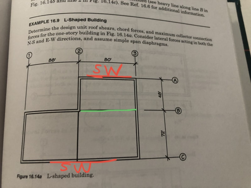
7A9143B2-AD2D-470A-A664-AA7C0EA7479D_u6kwtd.jpg


My question is May I treat the beam at line B as a collector (the green line) if there is no interior & exterior shearwalls on line B?

Thanks
 
Replies continue below

Recommended for you

OP said:
My question is May I treat the beam at line B as a collector (the green line) if there is no interior & exterior shearwalls on line B?

Normally, I'd say that the beam at line beam pretty much has to be a collector for EW seismic.
 
Thank you KootK.

This is what I confused. In my opinion, the collector should be at the line on which a shearwall is placed. If there is a shearwall at line B, the beam can be looked as a collector. Because collector can transfer the lateral forces from diaphragms both side to the shearwall at the line B.

On this case, there is no shearwalls at the line of the beam. The beam shouldn’t be considered as a collector. The lateral forces can be transferred to the exterior shearwalls at line A and C through the diaphragms both side. As long as the diaphragms are capable of the strength, the whole structure will be fine.
 
It's maybe a bit of semantics, but yes, I consider it a collector. Based on:
-size of inset (1 to 2, A to B) vs overall diaphragm dimensions
-resulting diaphragms on both side of GL B where a force transfer element collects shear

The whole structure won't be fine. There are no N/S shearwalls labelled and an irregular building shape with the corresponding size shown ought to have some sort of torsional stability to be fine.
 
Thank you skeleton

Please assume there is a shearwall at every line on the N-S direction coz I’d like to talk about the collector at E-W direction.

If the beam can be looked as a collector, which shearwall can resist the lateral force collected from the beam?
 
Can you put an isolation joint in the short wall, so the load is not transferred?

Rather than think climate change and the corona virus as science, think of it as the wrath of God. Feel any better?

-Dik
 
Thank you dik

This is not a real project. I just want to figure out the definition of a collector using this picture . In my opinion a collector should be at the same line with a shearwall. On this case, the beam should not be considered as a collector since there is no shearwalls at line B. Even the beam is designed as a collector, the lateral forces at E-W direction still are transferred to the shearwalls at line A&C through the diaphragms.
 
Because of the large transition in building shape, there should be a control joint in the vicinity and one on the opposite wall to be consistent.

Rather than think climate change and the corona virus as science, think of it as the wrath of God. Feel any better?

-Dik
 
For E-W seismic, the diaphragm is like a beam that spans between the shear walls at A and C. In this "beam," there is a shear, V, in kips at B.

V is assumed to be uniform between B-1 and B-3, so the diaphragm shear along B in lb/ft is v = V / (168 ft).

v between 1 and 2 must somehow make it to the shear walls at A and C. To make this happen, the member between B-1 and B-2 will have an axial load. From that, I'd say B-1 to B-2 is the collector along B in this scenario.

Edit: I looked for a definition of "collector," but in a few minutes I couldn't find a solid one. In ASCE 7-16, the following are helpful: Figures 12.10-1 and C12.10-1.
 
Hi 271828, your reply is helpful a lot.

In my opinion, the prerequisite for defining a collector is there a vertical element of LFRS at the same line with it. On this case, if a axial force can be developed on the beam at line B, there should be a shearwall at line B too. So the shearwall can receive the axial force of the beam.

Since there is no shearwalls on line B now. The lateral forces have to directly be transferred through the diaphragms to the shearwalls on A&C. And no axial force can be developed at line B even though there is a beam at here.(Is this idea correct?)

I agree some detailing needs to be done at the reentrant corner (Line2&B) but the reason should be stress concentration instead of axial force.

Any comments are welcome!
 
Draw a FBD of the portion of the roof between 1 and just to the left of 2. For EW seismic, the seismic force looks like a uniform EW horizontal force (traction, units are lb/ft^2) over this FBD. There must be an axial load in the beam between B-1 and B-2 for this FBD to be in EW force equilibrium. I think that's how we should decide if the beam from B-1 to B-2 is a collector.

Typically, a collector is in line with a shear wall, but not always. ASCE 7-16 Figure C12.10-1 shows an example of a collector that is not in line with a shear wall.
 
If the diaphragm left (west) of row 2 can transmit the E-W load to the diaphragm east of row 2, then I don't see how the beam on B "collects" anything. The A/C/2/3 diaphragm is not uniformly loaded, yes, but that's not a deal breaker. You could have the same uneven loading if there were nothing west of row 2 and the seismic weight of C to B were twice that of B to A.
 

For both reasons, and to simplify the analysis.

Rather than think climate change and the corona virus as science, think of it as the wrath of God. Feel any better?

-Dik
 
There are a number of ways you can look at this. I agree you should look up some more references on irregular diaphgrams in general though. I haven't done one in a while and they aren't always immediately obvious. You have to be really careful that you're providing a load path for everything.

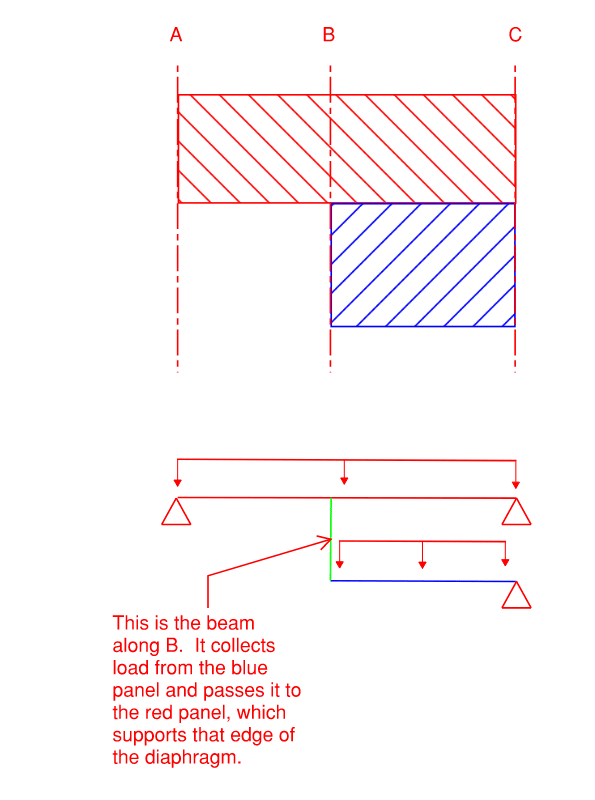
I've reoriented the structure so that we can imagine things as gravity loads. That sometimes helps me visualize load effects. Then I've drawn an attempt at an equivalent beam system. The red panel is the only one that spans between supports. There is a free edge on the blue panel. The blue panel is therefore supported by the red panel somehow. If we treat the beam along line B as a hanger, you can see that there will be a point load applied to the red panel equal to what would have been the support load on that side for the blue panel. It is a collector for the blue panel, transferring load into the red one, which spans it to the supports.

Diaphragm_mavg0x.png


Personally I'd have used the term drag strut for this, but I don't think that's functionally different.
 
Is this collector/drag strut design preferable to JLNJ's approach of a distributed load on the full-width diaphragm? I'd go distributed rather than concentrated unless persuaded otherwise.
 
I'd need to see more of what JLNJ is proposing. If the thought is that the section between one and two goes into tension/compression to get load into the main diaphragm, I don't think I'd agree with that? I'm not clear that this was what they were going for though.

I'll say that it looks like every example I see that is in Malone's "The Analysis of Irregular Shaped Structures" has a collector/drag strut in that type of location in buildings that are of this approximate layout. Also, the front half of the book is full of diagrams that include the note that all edges of a diaphragm should have a lateral resisting element of some sort to terminate the diaphragm.
 
I'd have something extra on grid B but don't think it necessarily needs to carry half the load in the C1-B2 panel. Capacity for half plus connection all along B2-C2 looks nice and safe though if no-one else on the project objects.
 
TLHS said:
...I've reoriented the structure so that we can imagine things as gravity loads. That sometimes helps me visualize load effects. Then I've drawn an attempt at an equivalent beam system. The red panel is the only one that spans between supports. There is a free edge on the blue panel. The blue panel is therefore supported by the red panel somehow. If we treat the beam along line B as a hanger, you can see that there will be a point load applied to the red panel equal to what would have been the support load on that side for the blue panel. It is a collector for the blue panel, transferring load into the red one, which spans it to the supports....
I agree. Good explanation.

Somehow or another, we have to establish equilibrium of every region. I don't see a way to do this without the beam between B1 and B2 having an axial load.

 
I don't think TLHS's model reflects how the structure works. The diaphragm would transmit that force from the blue section to the red internal to the diaphragm itself. There is no need for the green beam to "collect" anything. The green beam may be needed as a chord in the other direction, but that's not what the OP is asking.
 
Status
Not open for further replies.

Part and Inventory Search

Sponsor