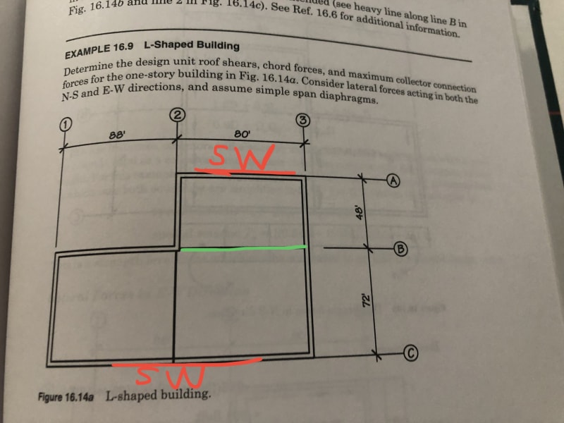
Please see the picture. Assume this is one story wood structure building under seismic control. The shearwalls are at exterior walls both side (the red lines)
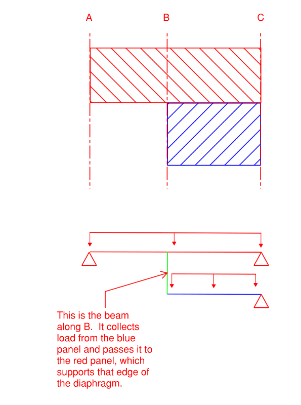
My question is May I treat the beam at line B as a collector (the green line) if there is no interior & exterior shearwalls on line B?
Thanks
My question is May I treat the beam at line B as a collector (the green line) if there is no interior & exterior shearwalls on line B?
Thanks