Continue to Site

Eng-Tips is the largest engineering community on the Internet

Intelligent Work Forums for Engineering Professionals

  • Congratulations KootK on being selected by the Eng-Tips community for having the most helpful posts in the forums last week. Way to Go!

Simultaneous position and establishing a clocking datum 1

Status
Not open for further replies.

sendithard

Industrial
Aug 26, 2021
166
I've got so many questions on this callout that it is better to ask questions over several posts Apologies for the rambling. The part I have is somewhat like the below picture. It is two less than half spherical cutouts inside a part. Disregard the idea of a feature of size as everything under the sun here is a fos.

The callout is simultaneous as the spheres are located basic to each other(and with same DRF) and then to the bore axis(datum A) and the bottom plane(Datum B):
0.05mm A|B so this is a spherical position callout located to the bore axis and a basic dimension to the bottom plane.

Our engineering team requires two positional outputs separately. So if the spheres are 6mm basic apart...We in essence are measuring them 3mm from the axis.

1) If you measure them separately...and they pass, does that mean they will pass simultaneously?
a) I played around in CAD with a 4 hole pattern and I couldn't really come up with a scenario where if they all pass individually, they would somehow fail together. This is where my lack of experience makes me question all my thoughts on this​

2) The clocking datum is not arrested so I am thinking about using the midpoint of the spheres as the clocking XY datum plane creation.
a) this would mean the spheres could be crooked compared to the rectangle nature of the part, but does this strategy creatively measure them simulteneously while still outputting them individually?​

3) Alternatively, if I use a midplane of the part as the clocking datum this would keep the sphere more true to the overall part, but then does that violate the simultaneous theory of the standard?

I'm a little confused here so I appreciate the guidance. I will be discussing with our overall leader soon, but I wanted to get your thoughts before I ask for a meeting. Functionality, and eliminating assembly errors trumps everything, but I'm asking for a technical take on the GDT and perhaps personal opinions.
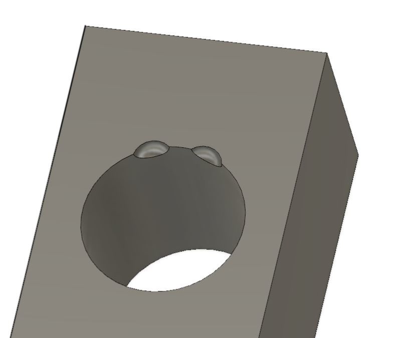
Capture_pdk8tq.jpg
 
Replies continue below

Recommended for you

pmarc,

10-4 appreciate the confirmation.

Alex,

I had a meeting recently where a positional callout was at MMC 0.0mm and the feature was a 120 deg torus with a radius at +- 0.025mm. They only gave me 0.05mm of bonus...on a diametrical positional callout...i told them whether you identify on Monday as a diameter or you wake up on a Tuesday feeling like identifying as a radius that the surface location is the same so I should get 0.100mm of bonus and they disagreed. Our engineers accept any callout the customer sends...im trying to push these callouts to surface profile as the position of the goofy features is a ficticious math based guess as you are indicating.
 
3dDave,

I agree with what you said, but I'm trying to push us into a more professional approach...these goofy irregular fos callouts are taxing.....


One thing to mention is our parts get plated and come back to us to get finally inspected for assembly so its not like the cat is hung out to dry.

My goal is less scrap and to remove the goofy positional callouts but I guess I need more company clout before they listen
 
My last question would be this on a technical side...

Whether you use the midpoint between both spheres to clock the XY datum or use the midplane of overall part....measuring both spheres for positional tolerance independently would or would not ensure they are in tolerance as a pattern?
 
How do you measure them at the same time? How many touch probes does the machine have or is this some sort of laser scan?
 
"a more professional approach" is to decline ambiguous work, except "professional" usually means getting paid.

Perhaps move to a company that doesn't accept garbage work from the engineers or get creative and let customers ask for help when parts don't fit.

If this was any typical professional interaction and the client refused advice, then that relationship would be severed.

Customer refuses new spark plugs when the old ones are badly eroded? Take it elsewhere.
Client keeps making outbursts in court and yelling at the judge? Ask to be relieved.
Patient says insulin is crap and the all-sugar diet from TikTok is great for diabetes? No more appointments and offer to send records to new doctor.

Not your fault and not your problem to fix - working around it supports the bad behavior.

You want less scrap - that is different from wanting parts that work - and that is why it is engineering's problem to fix.
 
Hi, 3DDave:

Yes. It does. A feature must have opposed sides to qualify as feature of size. For example, if included angle of a cylindrical feature is less than 180 degrees, then it is not a feature of size. Please see section 3.35.2 from ASME Y14.5-2018.

3.35.2 Regular Feature of Size
regular feature of size: one cylindrical surface, a spherical
surface, a circular element, or a set of two opposed parallel
line elements or opposed parallel surfaces associated with
a single directly toleranced dimension. See subsection 5.2
and para. 5.8.1(e).
 
Where is angle mentioned?

There is a spherical surface - doesn't say how much.
 
Dave......I don't give a shit about the standard or FOS or non FOS I care about one thing...if I measure each sphere idependently, will they fit as a group per my datums and the fact I am measuring them seperately
 
OP said:
,,,less than half spherical cutouts...

"Know the rules well, so you can break them effectively."
-Dalai Lama XIV
 
evan, I have sent specific recommendations to the committee to use - e.g. "Regular FOS exists only where directly opposing surface normals exist and exactly and only in line with those normals."

They did not explicitly exclude fractional surfaces and show no sign of doing so.

sendithard - Yes. Do it.

 
OP said:
If the main datum is the Bore, then can you measure each independently using basically a 3mm basic and know that if each pass independently that they will pass as a pattern.
When you see 4x positional callout at 0.05mm ABC can you measure each independently from the primary axis with the same clocking datum and be assured they pass as a group to the same 0.05mm ABC setup.


Pmarc and sendithard,

Could you, please, exlian explain what means "measure each sphere INDEPENDENTLY and how you could measure them as a "pattern"?
I am very much missing the point here.

I think I understand SIM REQT, but not those words and verbiage above.

Looks like pmarc agreed with the conclusion, but I am wondering what those statements meant

pmarc said:
pmarc (Mechanical)12 Oct 23 20:34
Quote (sendithard)
When you see 4x positional callout at 0.05mm ABC can you measure each independently from the primary axis with the same clocking datum and be assured they pass as a group to the same 0.05mm ABC setup.

Sounds like you are saying if they pass individually they pass as a pattern.

Yes, that's what I am saying.


You can measure each wannabe FOS spherical piece of surface separately or simultaneously (whatever that means) as long as you:
1. Consider that the tolerance zones have mutual basic location and not just location relative to the datum reference frame.
2. Don't manipulate the part in any available degrees of freedom or use any datum shift between each measurement.
 
Burunduk said:
You can measure each wannabe FOS spherical piece of surface separately or simultaneously (whatever that means) as long as you:
1. Consider that the tolerance zones have mutual basic location and not just location relative to the datum reference frame.
2. Don't manipulate the part in any available degrees of freedom or use any datum shift between each measurement.

I agree with that, but I am trying to understand what means in the OP's terms "separately or simultaneously (whatever that means)" ....
 
Simultaneous requirements does not mean that features have to be measured simultaneously, it means the features have to meet their requirement simultaneously. So you have to find the sweet spot where all the features are in tolerance simultaneously. You can't shift the part in one direction to get a few features to come into tolerance, then shift the part in another direction to get other features to come into tolerance.

For the record, I have to agree with the others here regarding this notion of these being forced to be FOSs when they absolutely aren't. Not even close. You don't care about the standard or FOSs but that's why you have this conundrum. Engineering can insist on doing things incorrectly all they want, it doesn't make it okay and it's not just because it breaks some rule in the standard. The rule is like that for a good reason. How are you going to evaluate that center anyway...least squares, outer tangential, inner tangential.? They will all give different answers. Get engineering to answer that question while they're at it.

John Acosta, GDTP Senior Level
 
I cannot agree more with your sentiment that it isn't a feature of size. I'm arguing tomorrow in a meeting about this issue.

My original question still is up for debate...

To measure each sphere simultaneously you would need to be SURE they are the within the basic distance from each other within stated positional tolerance.

In this example...If the clocking datum is not required....BUT there is a basic distance b/w both spheres, wouldn't you be required to clock to both spheres mid point if you were going to measure them seperately? If you used some other random plane you would not be able to associate the basic distances b/w each sphere in my opinion.

For instance...if both spheres are 10mm apart and I clock them b/w each other I can hard code the measurement to be separately 5mm apart.....BUT if I leave some other feature to clock them one feature may come in at a small value and another at a large value.....
 
3dDave,

I'm using both a CMM and CT scanner. CMM is more accurate point to point, but the CT is proving to be more accurate with assembly to summarize as it seems to be getting more surface area at an average correctly. You can measure hole simul on a CT. Whether you agree with the output is another thing.
 
In a hard gauge you would move that part to align all the part features and datum features to the corresponding gauge features at the same time.

FCFs and datum features tell which features should be aligned and how much movement the gauge fixture should allow to represent the least favorable variation allowed for by the mating part(s) and any additional margin the designers want.

How you arrive at mimicking that process with digitized measurements is up to you.

How would the approach work if there were 3 feature 120 degrees apart?

Two features and you can divide the manufacturing variation in half along one direction, but sometimes that means no way to also minimize the effect of radial variation; a possible situation can require giving up the alignment to put a radial variation back into the tolerance zone.
 
OP said:
In this example...If the clocking datum is not required....BUT there is a basic distance b/w both spheres, wouldn't you be required to clock to both spheres mid point if you were going to measure them seperately? If you used some other random plane you would not be able to associate the basic distances b/w each sphere in my opinion.

For instance...if both spheres are 10mm apart and I clock them b/w each other I can hard code the measurement to be separately 5mm apart.....BUT if I leave some other feature to clock them one feature may come in at a small value and another at a large value.....

In my opinion, the clocking could be done (if needed) by any "capable" feature as long as the relationship with the datum reference frame is basic. So, if you chose one sphere or both speheres or the width of the part or just a tangent point somewhere on the side of the feature will be equally good, as long as those points, widthds, center of spheres are BASIC to the DRF.

So, for the CMM measurement feel free to chose anything that is convenient to you, again just make sure you keep it basic to the already defined DRF.
As far as the simultaneous requirement I think Burunduk summarized it very good on how should be interpreted.

 
Before someone is pointing out "will be equally good" is on my latest replay is a relative term.
Will make in one case versus the other the design more stringent (than in the other case)

I think the most flexibility you will have when there is no clocking datum feature. As long as one clocking is "introduced" the design is (sometimes artificially) made more strict. (will be a little more limiting, for measurement purpose, than the actual design required)
 
Status
Not open for further replies.

Part and Inventory Search

Sponsor