Continue to Site

Eng-Tips is the largest engineering community on the Internet

Intelligent Work Forums for Engineering Professionals

  • Congratulations KootK on being selected by the Eng-Tips community for having the most helpful posts in the forums last week. Way to Go!

Simultaneous position and establishing a clocking datum 1

Status
Not open for further replies.

sendithard

Industrial
Aug 26, 2021
166
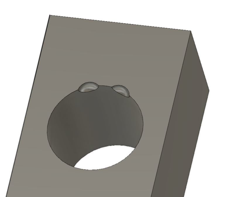
I've got so many questions on this callout that it is better to ask questions over several posts Apologies for the rambling. The part I have is somewhat like the below picture. It is two less than half spherical cutouts inside a part. Disregard the idea of a feature of size as everything under the sun here is a fos.

The callout is simultaneous as the spheres are located basic to each other(and with same DRF) and then to the bore axis(datum A) and the bottom plane(Datum B):
0.05mm A|B so this is a spherical position callout located to the bore axis and a basic dimension to the bottom plane.

Our engineering team requires two positional outputs separately. So if the spheres are 6mm basic apart...We in essence are measuring them 3mm from the axis.

1) If you measure them separately...and they pass, does that mean they will pass simultaneously?
a) I played around in CAD with a 4 hole pattern and I couldn't really come up with a scenario where if they all pass individually, they would somehow fail together. This is where my lack of experience makes me question all my thoughts on this​

2) The clocking datum is not arrested so I am thinking about using the midpoint of the spheres as the clocking XY datum plane creation.
a) this would mean the spheres could be crooked compared to the rectangle nature of the part, but does this strategy creatively measure them simulteneously while still outputting them individually?​

3) Alternatively, if I use a midplane of the part as the clocking datum this would keep the sphere more true to the overall part, but then does that violate the simultaneous theory of the standard?

I'm a little confused here so I appreciate the guidance. I will be discussing with our overall leader soon, but I wanted to get your thoughts before I ask for a meeting. Functionality, and eliminating assembly errors trumps everything, but I'm asking for a technical take on the GDT and perhaps personal opinions.
Capture_pdk8tq.jpg
 
Replies continue below

Recommended for you

pmarc, Burunduk, 3DDave and all,

Do you agree with my assessment above about the introduction of the clocking datum feature (lets pretend ONLY for measurement purposes) and the consequences of doing so? (meaning it is marking the design more stringent than the one without clocking datum feature)
 
More restrictions typically reduce solution space; this can simplify matters for CMM operators, complicate matters for gauge makers, not properly represent assembly constraints.
 
So looks like you agree with my assessment (about the strictness) ?

Anyone disagree with it?
I am trying to confirm if I am on the right track or already in the weeds.....
 
greenimi,

I agree with 3DDave here. One thing I would mention, though, is that there are cases where adding a clocking datum feature may not affect the design in terms of pass/fail geometrical conformance compared to the case with no clocking datum feature used.

To explain what I mean by all that, I will use fig. 7-21 in Y14.5-2018. If we imagine the figure is modified in a way that the pattern of 4 holes and the slot are both controlled with positions relative to |A|B|, this will be less stringent scheme in terms of relationship between the pattern and the slot than the scheme currently shown in the actual figure. This will be in line with your assessment.

But let's now imagine another scenario in which the tertiary datum slot in that figure is referenced at MMB, not at RMB, in the position callout for the pattern of holes and compare it with the scenario of the pattern of holes and the slot both controlled with positions relative to |A|B|, as already described above. In such a case, there would be no difference between the two scenarios in terms of pass/fail geometrical conformance. The difference, however, would most likely appear during the evaluation of the actual position values -- in the first scenario (datum slot C at MMB), the slot actual position value would be evaluated in the |A|B| candidate datum alignment but the actual position values for the pattern holes would be evaluated and optimized in a different |A|B|C(M)| candidate datum alignment; in the second scenario (all features relative to |A|B|), the actual position values for the pattern holes and for the slot would all be evaluated and optimized in the same |A|B| candidate datum alignment because of the default simultaneous requirements rule.
 
pmarc said:
In such a case, there would be no difference between the two scenarios in terms of pass/fail geometrical conformance

pmarc,
As usually you explained it well.
I still have a quick follow up question: why (based on what) are you stating that there is no difference between the two cases in the Scenario 2 (regarding pass/ fail acceptance criteria?

C at MMB as tertiary in the 4 hole pattern
slot = datum feature C
AND
4 hole pattern to A|B|
slot to A|B|

I have a little difficulty understanding this.

 
greenimi,

As usual, I agree with pmarc.

If C was referenced MMB,
-The TGC (datum feature simulator) for C would be a tab of virtual condition (VC) size (8.0) at its basic location
-The gage element for the hole pattern would be 4 VC size (7.3) pins located at their true positions
-The holes would have to fit over their pins in one of the candidate datum reference frames allowed by the datum feature shift on C

If the slot and hole pattern were both controlled relative to |A|B|,
-The gage element for the slot would be a tab of VC size (8.0) located at its true position
-The gage element for the hole pattern would be 4 VC size (7.3) pins located at their true positions
-The slot and the hole pattern would have to fit over their gage elements in the same candidate datum reference frame, because of simultaneous requirements

So in terms of pass/fail conformance, the two scenarios are the same.

Evan Janeshewski

Axymetrix Quality Engineering Inc.
 
In the MMC/equivalent cases is making a more elaborate version of the OP problem - having to find a solution to the clocking problem that satisfies all requirements.
 
Evan said:
The holes would have to fit over their pins in one of the candidate datum reference frames allowed by the datum feature shift on C

Why describe datum shift in terms of multiple candidate datum reference frames? This is kind of explainable, but may complicate things unnecessarily.
The way I see it, there is only one datum reference frame, fixed relative to the datum feature simulators and the datums and established based on them. The part to datum reference frame relationship is what can vary within the allowed shift and have "candidates".
 
There is no datum shift in this example, I don't want to even think about that right now.

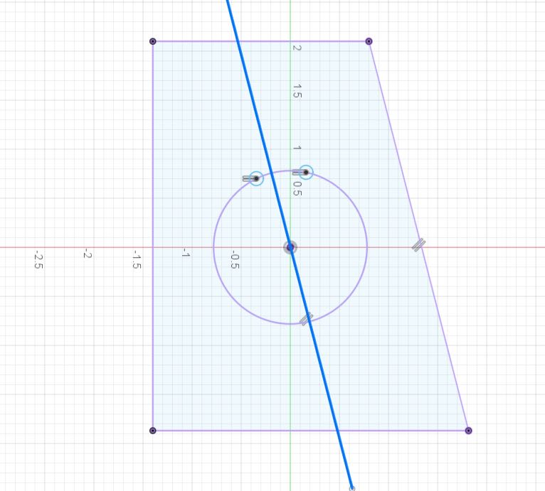
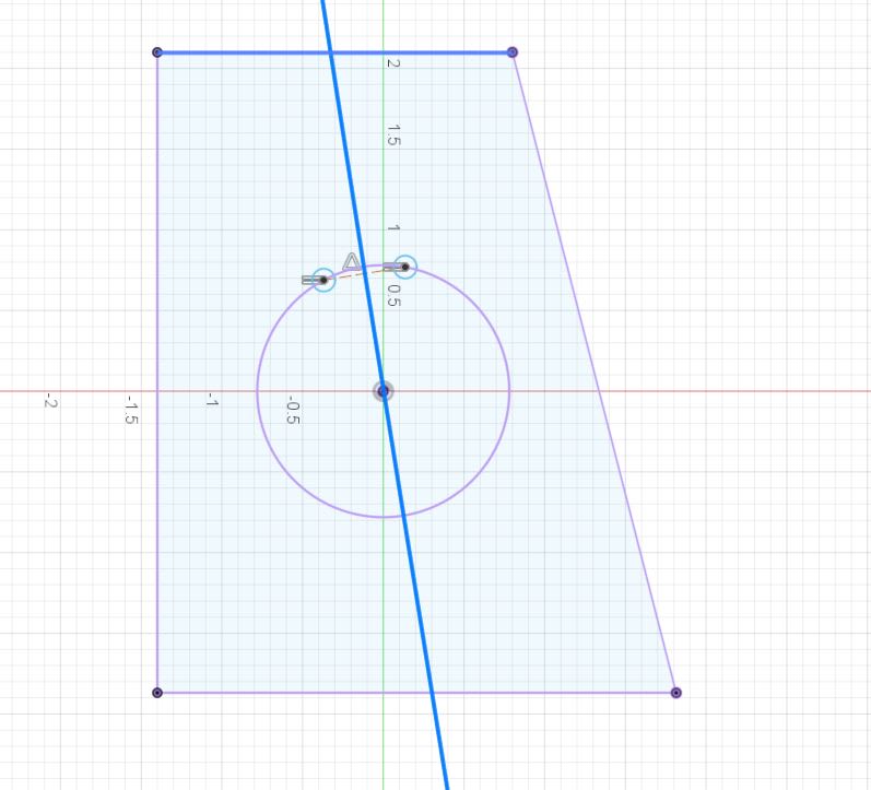
I initially conceptually agreed with greenimi, that the clocking datum doesn't matter when reporting out the spheres separately to make sure they are conforming simultaneously, but let me share a quick CAD rough sketch that makes me think otherwise...

If you report the sphere separately you must apply half their stated BASIC dimension from each other to the clocking Datum. That is what concerns me....The easy solution is what I am doing right now is that I use the midpoint from both sphere to clock to insure simulaneous, but manufacturing doesn't like that I output the same distance from that axis at nearly the same value for both spheres.

In the top picture, lets assume you used one side surface as the clocking datum(bad idea obviously as a midplane would be better, but let's spitball) and it was just milled at a terrible angle...this is what you would get. Yes both spheres in both clocking datums are the same distance apart, but if you measure them separately you must use half the basic dimension so not using the mid point seems wrong to me.

In the 2nd pic I use the mid point of both spheres to clock to make sure I measure them equally from the clocking datum to ensure a simultaneous convention.

Capture_v33z1y.jpg
2222222222_yjh6qb.jpg
 
sendithard said:
If you report the sphere separately you must apply half their stated BASIC dimension from each other to the clocking Datum.


Why? If what you care about is the distance between them, why do you have to split that distance equally? For example, if the nominal spacing between the spheres is 6 mm, does it matter if they are 3 mm and 3 mm or 4 mm and 2 mm from the plane you clock to?
 
Burunduk,

You are correct if manually checking the part. But I'm writing a program that must check 100 parts per week, run by operators, without any manual input or overrides. Therefore, to check them individually, I need to tell the software how far from a datum plane each sphere sits so I can apply a measurement output value to each spheres position separately. I can't let one sphere wonder around 1mm from an arbitrary clocking datum and then the other one float to 5mm. I need to set a distance from each that is static, so I would need to set it to 3mm from my analysis.

I'm just wondering if what I'm saying about using the midpoint of both spheres to clock is the only correct way to repeatably measure both spheres individually using a program that cannot change location or tolerance values and make sure they are passing if done simultaneously.
 
Wait a minute...I'm a complete idiot. If you use a poorly machined plane for the clocking you could still input 3mm for each sphere, it would just force the spheres to clock to that surface.

Sometimes, I'm stupid.

I guess where I kept getting hung up is if there is this simultaneous requirement not only by the standard, but for fit and functionality, then if all features pass individually, why in the world would we need the distinction of a simultaneous convention?

If you didn't know the rule, and measured them simul, your are fine....and again if you didn't know the rule and you measured them separate you are also good. So why the rule?
 
OP said:
....and again if you didn't know the rule and you measured them separate you are also good. So why the rule?


Because, (and I am copying from Burunduk's replay) you are NOT alllowed to "manipulate the part in any available degrees of freedom or use any datum shift between each measurement."

 
greenimi,

I think I may be seeing the light...

If you have a 4 hole pattern and there is no datum shift modifiers, there really is no difference in measuring them individually vs as a pattern for the ultimate fit and functionality.

BUT...if there are datum shift modifiers you would be required for the fit and functionality to measure them as a pattern WITH DATUM SHIFT allowed.....or measure them individually with a single one-shot, one kill datum shift, and that datum shift would need to be set in stone to measure them individually....ie if you measure them individually you can datum shift once and that is it, no more movement. Correct?
 
sendithard, yes.
And same for using any available degrees of freedom.

sendithard said:
....and again if you didn't know the rule and you measured them separate you are also good. So why the rule?

Imagine a simple cylindrical pin with two end faces normal to the axis. You could use the diameter of the pin as datum feature A and profile each end face with ref. to A. The relationship of each face to datum axis A is only perpendicularity, and that is what you would be controlling IF you overrode the default by SEP REQT. But with the simultaneous requirement default, you are also essentially controlling the length of the pin (when the length dimension is basic).
 
This line of questions may be exactly why the GDTP exam is not worthwhile.

This is all basic concepts and sendithard says he got 90%, so why the problem?

Are there no questions about practical applications on the exam?

This is a fundamental concept and a 1940s core concept, before explicit datum symbols existed.

sendithard worked hard to pass that exam, but I think the ASME system has failed him greatly.
 
The exam doesn't guarantee zero questions or that you no longer need to learn. When one keeps learning after receiving whatever certification, it's a sign of professionalism. Unlike claiming that the standard is wrong every single time you don't get something.
 
OP said:
BUT...if there are datum shift modifiers you would be required for the fit and functionality to measure them as a pattern WITH DATUM SHIFT allowed.....or measure them individually with a single one-shot, one kill datum shift, and that datum shift would need to be set in stone to measure them individually....ie if you measure them individually you can datum shift once and that is it, no more movement. Correct?

OP said:
....there is no datum shift modifiers, there really is no difference in measuring them individually vs as a pattern for the ultimate fit and functionality.

Another example, in addition to the one provided by Burunduk, is, for example, if a DRF is |A|B|C| (----all of them regardless of material boundaries hence no datum feature shift from any of the datum features depicted in the DRF----) and datum feature A is a planar feature which might be rocking (convex feature) then you can chose only one "candidate" -1994, 2009,(from the infinity of those available created by your primary datum feature which again is a rocker) and all the features defined based on |A|B|C| must be in their respective tolerance zones.

copy-paste from different thread
"I would contend that your choice of datum planes is only one of an infinite number of candidate datum planes (to use Y14.5.1 terminology) and that you have a "rocker." In instances where we have candidate datum planes, the standard allows us to "optimize" and choose *the* datum plane that best suits our specification/application. I could have a mobile coordinate system for any reason, such as a datum feature of size referenced at MMB, and find an infinite number of candidate locations of the datum reference frame where the measurements would be out of spec. The point of optimization is to find the place that works, not to demonstrate the plethora of places that don't work."

Foot note: (very unimportant for the OP and for this discussion, but just to keep the record straight)
"the 2018 version changed the default stabilization procedure from candidate datum set to single solution to minimize separation) – 2018 states: “the default requirement is that the part be adjusted to a single solution that minimizes the separation between the feature and the true geometric counterpart”…" Whatever that means (CMM won that fight) we will see in the near future..........
 
Burunduk said:
Imagine a simple cylindrical pin with two end faces normal to the axis. You could use the diameter of the pin as datum feature A and profile each end face with ref. to A. The relationship of each face to datum axis A is only perpendicularity, and that is what you would be controlling IF you overrode the default by SEP REQT. But with the simultaneous requirement default, you are also essentially controlling the length of the pin (when the length dimension is basic).

Are you sure, Burunduk, that your statements are correct?
 
"The exam doesn't guarantee zero questions or that you no longer need to learn.

Nor does it appear to ensure that those who pass understand the most basic of reasons for the creation of true position tolerancing.

The test used to be a parrot test - a test ChatGPT would get 100% on. My opinion then was it would lead to results like this, mainly as I knew 3 takers, one of whom failed to choose suitable datum references on a regular basis, and also because, when I pointed out a significant error in the ASME teaser test, ASME took the test off their website. I pointed this out to a long-standing member of the committee. This does not improve that opinion.

The standard is wrong because I do get something - it's not right just because you can copy/paste fragments in a manner similar to a ransom note.
 
Status
Not open for further replies.

Part and Inventory Search

Sponsor