Eng-Tips is the largest engineering community on the Internet

Intelligent Work Forums for Engineering Professionals

Single datum axis of a single spool containing 04 bearings made by 04 shafts spline coupled 2

Status
Not open for further replies.

giangnguyen92

Aerospace
Oct 3, 2019
20
0
1
VN
Hi everyone,
I am a young engineer so I would like to ask you guys’ experience in real practice cases.
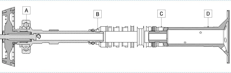
At the moment I am analyzing a gas turbine spool containing 04 shaft sections spline coupled and there are 04 bearings on the spool. Three (03) of those bearings are on the same axial positions as corresponding couplings. This structure is very typical in gas turbine design.
As the common approach, I set 4 bearing seats on the spool as datum features, called A, B, C and D from left to right.

I now want to set runout tolerance for each datum features based on the single axis.

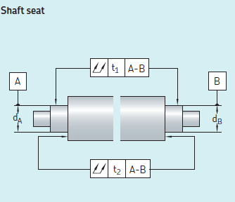
However, the following practice from bearing manufacturer SKF mentions only the case in which the single datum axis is established from two (02) cylindrical datum features ONLY (2 bearings on a spool). Fig 4-25 and 9-4 ASME Y14.5-2009 mention similar cases.
Shaft_seat_runout_kzrjxr.png


Therefore, I would like to ask how I can establish the single datum axis here? And how I can check these runouts in reality?

I feel that setting A-B-C-D as a single datum axis is over-constrained. Am I correct?

Some of my thoughts:
1. Setting A-D (the first one and the last one) as a single datum axis. Checking in reality is based on 2 V-blocks putting on datum features A and D only. Am I correct?

2. Setting pair by pair: A-B, B-C and C-D. So that designing and checking runout is based on corresponding positions. For example: runout designing and checking of datum features B and C are based on the single datum axis B-C and corresponding V-blocks putting on datum features B and C. Consequently checking for 02 other pairs, all 04 datum features runout are checked.

I am looking for your experienced comments.
Thanks for your help.

P/S: I noted that unlike multiple bearings case on a spindle axis where they are designed very close to each other, these 04 bearings on a gas turbine spool is 300 mm-500 mm away from each other, far enough to be considered as separate datum features.
 
Replies continue below

Recommended for you

giangnguyen92,

I am familiar with ASME Y14.5. You may be working to some other standard.

You have applied run-out specifications to your datum features. This is a way to control circularity if it is very much more critical than your diameter tolerance. If these are surfaces for bearings, the diameters are accurate features of size, and circularity is controlled by Rule[ ]#1.

The run-outs specified on the perpendicular faces are meaningful as per ASME Y14.5-2009, the standard I just pulled off my bookshelf, and they are measurable. Is this really critical?

If I had to measure this thing, I would sit your datum features on a pair of V-blocks, and use a dial indicator on the faces.

--
JHG
 
giangnguyen92,

You are asking about datums[ ]A, B, C and[ ]D. I only see[ ]A and[ ]B. As per ASME Y14.5, the two datum features together define a centre axis. If you define one of the perpendicular faces as datum[ ]C, you will have immobilized your part. This is what datum features must do.

If you have additional centreing features[ ]C and[ ]D, you are over-constraining your part. Any additional round features ought to be centred on [A-B]. Going [A-B], [B-C] and then [C-D] makes no sense to me unless your shaft is flexible.

--
JHG
 
giangnguyen92,

Can you post an image showing a section view of the spool assembly with the bearing seats and spline connections labeled?

Do you intend to treat the spool assembly as a single rigid body for the purpose of these runout tolerances?

Is the runout of the assembly significantly controlled by the assembly process, or is it essentially predetermined by the geometry of the four individual shaft sections?

Is ASME Y14.5-2009 the drawing interpretation standard you are using? If not, please specify.


pylfrm
 
Dear drawoh,

"The run-outs specified on the perpendicular faces are meaningful as per ASME Y14.5-2009, the standard I just pulled off my bookshelf, and they are measurable. Is this really critical?"
Yes, it is what required by the bearing manufacturer such as SKF. So I think these axial runout are critical.

"If I had to measure this thing, I would sit your datum features on a pair of V-blocks, and use a dial indicator on the faces."
Yes, this is what I imagine I will do.

 
Dear drawoh,

"You are asking about datums A, B, C and D. I only see A and B. As per ASME Y14.5, the two datum features together define a centre axis. If you define one of the perpendicular faces as datum C, you will have immobilized your part. This is what datum features must do."

No, I do not set datum features on perpendicular faces.
The picture I attached above in which you see only A and B is what I snipped from SKF document.

"If you have additional centreing features C and D, you are over-constraining your part. Any additional round features ought to be centred on [A-B]. Going [A-B], [B-C] and then [C-D] makes no sense to me unless your shaft is flexible."

I have 4 bearing shaft seats, from front to back called A, B, C and D. A is where I install the first bearing and D is where I install the last one.
Thank you for your comment that setting more datum to form a single datum axis like A-B-C-D is over-constraining.
My spool (containing 4 shafts spline coupled) is the rigid one. So I agree with your advice that getting many pair is unnecessary.
And I will take A-D (the first and the last shaft bearing seats) as the single axis datum.
 
Dear pylfrm,
"Can you post an image showing a section view of the spool assembly with the bearing seats and spline connections labeled?"
I attach here its picture for you guys' reference. I have to hide many of its details but I hope that it is still clear enough for my question. A, B, C and D are marked as datums corresponding to bearing shaft seats, respectively.
Engine_spool_rsyupd.jpg


"Do you intend to treat the spool assembly as a single rigid body for the purpose of these runout tolerances?"

Yes, the spool is intended to be a single rigid body by spline coupling. It is not like a flexible body of shafts connected by a quill shaft.

"Is the runout of the assembly significantly controlled by the assembly process, or is it essentially predetermined by the geometry of the four individual shaft sections?"
These runout is intentionally predetermined by the geometry of all four individual shaft sections, designed coupling and fit between them (of course, if we design it correctly).

Is ASME Y14.5-2009 the drawing interpretation standard you are using? If not, please specify.
I read both ASME 14.5Y 2009 and ISO 1101:2017 and I found no difference in runout definition between these two documents. Thus, I feel that using either of them will have the same meaning, am I correct?

Thanks for your replies.
 
These runout is intentionally predetermined by the geometry of all four individual shaft sections, designed coupling and fit between them (of course, if we design it correctly).

If the runout is actually controlled at the individual part level, what is the purpose of runout tolerances at the assembly level?


I read both ASME 14.5Y 2009 and ISO 1101:2017 and I found no difference in runout definition between these two documents. Thus, I feel that using either of them will have the same meaning, am I correct?

The difference relates to the datum feature references. ASME Y14.5-2009 is somewhat vague on the subject. ISO goes into more detail in ISO 5459:2011, but it's not perfect either.


pylfrm
 
Dear pylfrm,

"If the runout is actually controlled at the individual part level, what is the purpose of runout tolerances at the assembly level?"

Let me explain more:
- Things will be simple if the spool is a single shaft with 2 bearings (no assembly), one at each its end. Supposed their corresponding shaft seats are A and B. And then the single axis datum will be A-B and each datum A, B's runout will be determined based on this single axis A-B datum and V-blocks.

- My spool is formed by 4 spline coupled shafts. The rotating axis now is no longer each individual shaft's one (theoretically) but the spool's final axis. Runout control of each shaft seats (datum) is based on the spool's single datum axis and as far as I understand it is only meaningful if it is compared to the mutual axis.

For example: if considering the whole spool assembly, runout of the datum D will be measured relative to the spool's single axis datum (this is what I want to ask in this topic, how to establish it).
However, the shaft having datum D has only 1 bearing seat, so we simply can't measure runout of datum D in the shaft alone where datum axis is D also.
 
giangnguyen92,

It looks to me like you have two pieces. Each piece requires its own fabrication drawing and datums. I don't think the datums mean anything at the assembly level you have shown. It looks like your pieces will be centred by your spline coupling, which creates a separate set of dimension and tolerance issues.

--
JHG
 
Dear drawoh,

Between B and C is the continuous, single shaft. It looks like that because I over-delete some details because my colleagues ask.
Let me make it clear:
On the left hand side of A is the 1st shaft (grey color)
Shaft seat A is on the 2nd shaft, this shaft is spline coupled to inner diameter of B (on the 3rd shaft)
Shaft seats B and C belong to the 3rd shaft.
Shaft seat D is on the 4th shaft. This shaft is spline coupled to inner diameter of C (on the 3rd shaft)

Beside coupling for torque transportation, at the shafts' contacting area there are "locational transition fit" area for straightening shafts.

Due to the properties of these coupling, these 04 shafts form a solid, single spool (this is what we intend to make).
It is not "two pieces" as you thought.

Here I want to install bearings. Requirements from bearing manufacturer SKF, their single datum axis establishment is for single shaft with 02 bearing. Now I want to expand their concept to a single solid spool (but multiple shafts spline coupled).
From your point of view, the single axis datum A-D would be correct, am I right?
Choosing A-B-C-D as single axis datum would be over-constraining, am I right?
 
However, the shaft having datum D has only 1 bearing seat, so we simply can't measure runout of datum D in the shaft alone where datum axis is D also.

Presumably you could measure runout of datum feature D with respect to D-E, where datum feature E is the feature on the left end of the 4th shaft that locates it relative to the right end of the 3rd shaft. Similarly, you should be able to measure runout of datum feature A with respect to A-F, where datum feature F is the feature on the right end of the 2nd shaft that locates it relative to the left end of the 3rd shaft. Runout of datum features B and C on the 3rd shaft could be measured with respect to B-C, just like the SKF image shows. These runout tolerances would all be specified on the individual shaft section drawings.


Beside coupling for torque transportation, at the shafts' contacting area there are "locational transition fit" area for straightening shafts.

Due to the properties of these coupling, these 04 shafts form a solid, single spool (this is what we intend to make).

Locational transition fits typically allow some clearance. Treating the spool assembly as a single rigid body seems rather questionable if that's the case. Maybe I'm missing something though. I'm not familiar with these machines.


Choosing A-B-C-D as single axis datum would be over-constraining, am I right?

It may be overconstraint in a mechanical sense, but that doesn't mean it would be an invalid specification on a drawing. You need to decide whether the meaning defined by whichever standard you use is sufficiently clear and matches what you want to achieve.


pylfrm
 
Dear pylfrm,

"Presumably you could measure runout of datum feature D with respect to D-E, where datum feature E is the feature on the left end of the 4th shaft that locates it relative to the right end of the 3rd shaft. Similarly, you should be able to measure runout of datum feature A with respect to A-F, where datum feature F is the feature on the right end of the 2nd shaft that locates it relative to the left end of the 3rd shaft. Runout of datum features B and C on the 3rd shaft could be measured with respect to B-C, just like the SKF image shows. These runout tolerances would all be specified on the individual shaft section drawings."
Thanks for your suggestion, it could be an useful solution.
However, your response brings me to the broader question: how things will be manufactured in reality? i.e. conditions of manufacturing set-up and control

I mean, shafts are manufactured piece by piece instead of the whole spool assembly. In this sense, in order to achieve runout specifications on each datum features A, B, C and D as final specifications; each shaft needs to be controlled of runout on A, B, C and D separately first, right?
Therefore, each shaft needs another datum feature in order to establish a single datum axis so that runout in main datum features (A, B, C or D) will be controlled relative to this single datum axis, right?

If I think in terms of manufacturing aspects above, your suggestion is extremely useful. And in principle, datum axes D-E and A-F must be identical to A-D via straightening/aligning fits between shafts, right?

And then finally, if taking A-D as the single axis datum without controlling runout on individual shaft. If runout specifications are not met at the spool assembly level check, we can't correct them, right?
 
Dear pylfrm,

"Locational transition fits typically allow some clearance. Treating the spool assembly as a single rigid body seems rather questionable if that's the case. Maybe I'm missing something though. I'm not familiar with these machines."

Yes, you are right, I just checked it again. The fit is interference fit type for purpose of rigidity and alignment.
 
Status
Not open for further replies.
Back
Top