giangnguyen92
Aerospace
- Oct 3, 2019
- 20
Hi everyone,
I am a young engineer so I would like to ask you guys’ experience in real practice cases.
At the moment I am analyzing a gas turbine spool containing 04 shaft sections spline coupled and there are 04 bearings on the spool. Three (03) of those bearings are on the same axial positions as corresponding couplings. This structure is very typical in gas turbine design.
As the common approach, I set 4 bearing seats on the spool as datum features, called A, B, C and D from left to right.
I now want to set runout tolerance for each datum features based on the single axis.
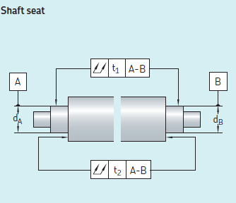
However, the following practice from bearing manufacturer SKF mentions only the case in which the single datum axis is established from two (02) cylindrical datum features ONLY (2 bearings on a spool). Fig 4-25 and 9-4 ASME Y14.5-2009 mention similar cases.

Therefore, I would like to ask how I can establish the single datum axis here? And how I can check these runouts in reality?
I feel that setting A-B-C-D as a single datum axis is over-constrained. Am I correct?
Some of my thoughts:
1. Setting A-D (the first one and the last one) as a single datum axis. Checking in reality is based on 2 V-blocks putting on datum features A and D only. Am I correct?
2. Setting pair by pair: A-B, B-C and C-D. So that designing and checking runout is based on corresponding positions. For example: runout designing and checking of datum features B and C are based on the single datum axis B-C and corresponding V-blocks putting on datum features B and C. Consequently checking for 02 other pairs, all 04 datum features runout are checked.
I am looking for your experienced comments.
Thanks for your help.
P/S: I noted that unlike multiple bearings case on a spindle axis where they are designed very close to each other, these 04 bearings on a gas turbine spool is 300 mm-500 mm away from each other, far enough to be considered as separate datum features.
I am a young engineer so I would like to ask you guys’ experience in real practice cases.
At the moment I am analyzing a gas turbine spool containing 04 shaft sections spline coupled and there are 04 bearings on the spool. Three (03) of those bearings are on the same axial positions as corresponding couplings. This structure is very typical in gas turbine design.
As the common approach, I set 4 bearing seats on the spool as datum features, called A, B, C and D from left to right.
I now want to set runout tolerance for each datum features based on the single axis.
However, the following practice from bearing manufacturer SKF mentions only the case in which the single datum axis is established from two (02) cylindrical datum features ONLY (2 bearings on a spool). Fig 4-25 and 9-4 ASME Y14.5-2009 mention similar cases.

Therefore, I would like to ask how I can establish the single datum axis here? And how I can check these runouts in reality?
I feel that setting A-B-C-D as a single datum axis is over-constrained. Am I correct?
Some of my thoughts:
1. Setting A-D (the first one and the last one) as a single datum axis. Checking in reality is based on 2 V-blocks putting on datum features A and D only. Am I correct?
2. Setting pair by pair: A-B, B-C and C-D. So that designing and checking runout is based on corresponding positions. For example: runout designing and checking of datum features B and C are based on the single datum axis B-C and corresponding V-blocks putting on datum features B and C. Consequently checking for 02 other pairs, all 04 datum features runout are checked.
I am looking for your experienced comments.
Thanks for your help.
P/S: I noted that unlike multiple bearings case on a spindle axis where they are designed very close to each other, these 04 bearings on a gas turbine spool is 300 mm-500 mm away from each other, far enough to be considered as separate datum features.

