Continue to Site

Eng-Tips is the largest engineering community on the Internet

Intelligent Work Forums for Engineering Professionals

  • Congratulations waross on being selected by the Eng-Tips community for having the most helpful posts in the forums last week. Way to Go!

Slab analysis as 3D shell element versus 1m strip beam element 2

Status
Not open for further replies.

ITsSB

Structural
May 6, 2022
30
I have a 30mx13m Rapid Sand filter and a valve room (part of a water treatment plant) as indicated on the image below.
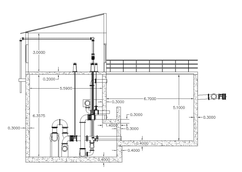
RSF-Section_roohvm.jpg

[URL unfurl="true"]https://res.cloudinary.com/engineering-com/image/upload/v1666258926/tips/RSF-3D_yxwb3k.bmp[/url]
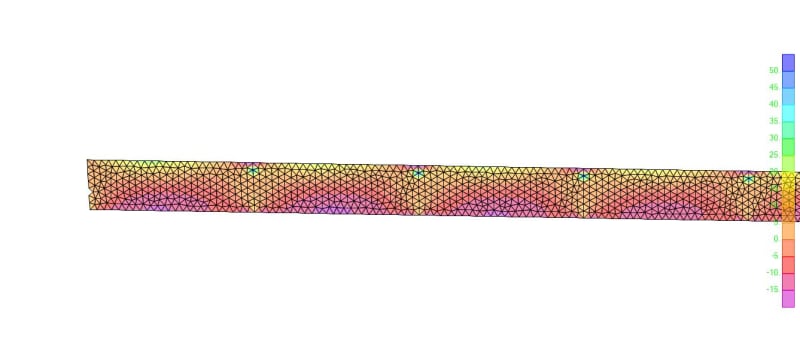
RSF-Overhang-Moment-Contour_rkenwm.jpg

I have modelled the entire structure as 3D on gmsh (a meshing software) meshed the shells there and imported to sap2000 and added the columns at a joint for analysis. But one side of all columns and the wall supporting the interior column are all supported on 1.4m Long RC slab. I know it is not ideal to support it that way and that wall resting on the 1.4m slab should have to extend all the way to the foundation but it is near impossible because there are pipes and pipe fittings and a lot of valves. So, I had to see if I can support it this way. But I was expecting the negative top moment at that overhang slab to be relatively large but I am not getting the results I'm expecting. So, just to see some conservative result, I took the 1.4m long overhang slab as a 0.3m deep by 1m strip beam and modelled it with the right side fixed.
For the loads:-
1. I took half the 0.2m deep slab weight (for convenience) and adjusted it for a 1m strip and it is 14.4KN point load
2. For the HCB wall I took full weight of 3m height wall and is 11.7KN point load
3. For the 5kN/m2 Live Load on the top slab I took 7KN point load
4. For the wall self weight I took its weight on 1m strip as 28.8KN Point load
5. There is a 3.45m deep water load on the slab so I took 34.5KN/m distributed load for that

The result resembles what I'm expecting. Maximum support moment is around 144KN.m (about Φ20 @ 140mm)
For comparison, The result from the full 3D FEA analysis is only about 50kN.m for the top support moment on the overhang slab (around
Φ12 @ 170mm )
So is this acceptable why is there so much difference I know the 3D anlysis had to distribute to all members and had to be a little bit lower but is the difference not huge?
 
Replies continue below

Recommended for you

I suspect the reason to be that there is no "overhang beam" (cantilever) in the structure. It seems connected to two walls in the figure you provide and is thus part of a building frame, which will obviously cause different bending moment distribution than a cantilever.
 
@centondollar I think you are right, also the deflection at the left cantilever(ish) slab is too small (close to fixed support) further justifying your answer. And now that i think about it, 144kN.m/m seems a little exaggerated too. But, I'm still not convinced as the 50kN.m/m from the 3D FEA analysis feels a bit too small and risky. But again I could be wrong.
 

Mr Simeneh (Civil/Environmental),

Just by screening , my opinion is, there are some mistakes at modelling and loads;

- The subject wall ( 0.3X3.0 L= 30 m ) essentially a deep beam having span 30.0 m,
- The subject cantilever slab (0.3 , L=1.4 m ) partially supported by the deep beam rather than supporting the wall except some moment transferred to the mat ( apparently 50kN.m/m )

- You did not account the filter material lateral load ..

I think the filter unit should not be a single cell but composed of 5-6 cells with partition walls..

If this is true , I will suggest you to extent partition walls to support the subject wall or provide some local butresses btw under the wall and mat ..


Tim was so learned that he could name a
horse in nine languages: so ignorant that he bought a cow to ride on.
(BENJAMIN FRANKLIN )

 
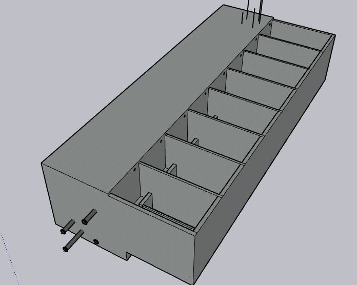
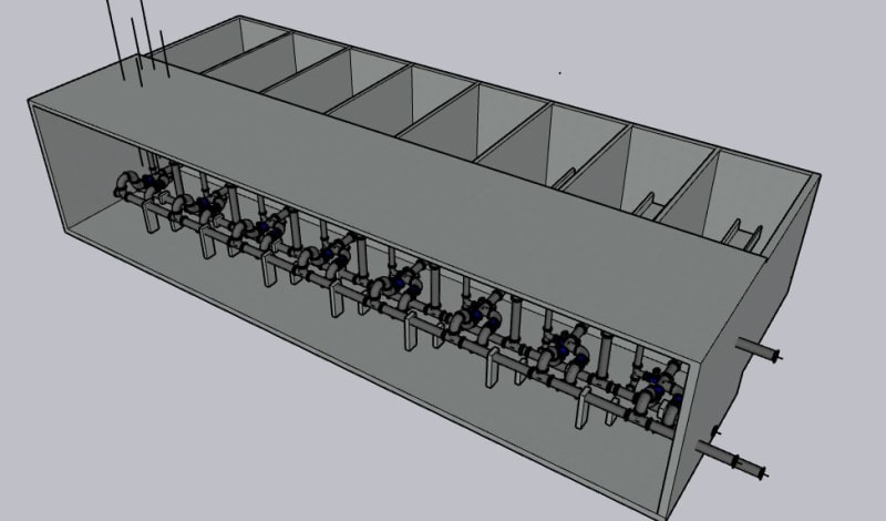
@HTURKAK Thank you for your answer, The sand filter is composed of 8 compartments (units) each 3.6m wide. sorry for not attaching the plan earlier(I thought the compartments are visible on the 3D model I shared before)The internal partition walls look like the following image.
Front_Perspective_olwjxa.jpg

Rear_Prespective_shvqo9.jpg

The filter material which is basically 0.85m sand (unit weight 19kN/m3 and active earth pressure constant ka = 0.27) and 0.6m deep gravel (unit weight 16kN/m3 and ka = 0.27)
1. for the sand, 0.27x0.85mx19kN/m3 = 4.4kN/m2 triangular load
2. for the gravel, 0.27x0.6mx16kN/m3 = 0.97kN/m2 triangular load
I thought the lateral load due to the gravel and sand is negligible on the wall but clearly its not. But I did include the loads on the mat. Also I was ignoring the response from the internal partition wall on the cantilever slab since part of the internal portion of the wall (to the right of the cantilever slab) is fixed to the mat. So when I modelled the 1.4m long cantilever slab as a beam, I assumed only one direction load transfer (short direction only) making my moment huge (144KN.m/m).
I know it would be best to extend those internal walls down If I could, but, if I'm making the decision to move the valves and pipes away from its bottom axis, I think I should have a better explanation than say "to make it safe" because the 3D FEA anlyis says otherwise. what do you think? (Also personally I'm curious too, If it can be done, why shouldn't be done like this)

Edit: also the sand and gravel rests only on the mat and not the cantilever portion.
 

Apparently, the latest isometric pic. shows that the subject wall is supported by partition walls rather than cantilever slab ..and the 3D FEA analysis ( 50kN.m ) seems correct..


This assumtion is true for normal operation.. during back washing, totally different..

My points ;

- The lateral loads from hydrostatic + sand fill+ gravel fill shall be considered.. The lateral pressure (if water ht 3.0m) at the bottom ; 30+ 4.4+ 0.97 = 35.4 kN/m2 for normal operation,

- During back-wash operation, The lateral and vertical loads for water and filter material totally different story .. pls get info . from piping and pump designers.. ( back- wash water pump discharge pressure could be assumed for design)..

My OPINION ...


Tim was so learned that he could name a
horse in nine languages: so ignorant that he bought a cow to ride on.
(BENJAMIN FRANKLIN )

 
@HTURKAK Sorry for the late reply, Thank you for you reply it was helpful. I included the lateral filter (sand+gravel) load on the wall. I then took the full depth of Sand filter for maximum water pressure calculation (both for back-wash and normal filtration) on the Sand filter wall. That should put me on the safer side.
"back-wash water pump discharge pressure could be assumed for design" isn't that the same thing as the backwash water level times unit weight of water? so,
1. 2.6mx10kn/m3 = 26kN/m2 triangular load for water
2. 4.4 +0.97 (lateral load due to filter material)

I'm not sure what you meant but, I took the full 5.1m head of water pressure for the wall design. (back-wash water head in the tank is only 2.6m) if the backwash pump is pumping water from the -10m do you mean I need to use that 10+2.6 = 12.6m water head for the wall design instead of the 2.6m water head?
 

No...not really.. The back wash water pressure at the spill level is absolutely zero , but at the bottom of the filter , 8 at bottom of gravel ) it is totally different story..

If you control the outlet pressure of the back wash water pump ( say wit open surge tank ) , you may assume the bottom pressure is the max. water level at surge tank . If you limit the max .level to (say 5.1 m) at the surge tank, it will not be possible to back wash the filter..

Again , i will suggest you to speak with pump and piping engineers..


Tim was so learned that he could name a
horse in nine languages: so ignorant that he bought a cow to ride on.
(BENJAMIN FRANKLIN )

 
@HTURKAK I understood what you meant thank you for your answer.
 
Status
Not open for further replies.

Part and Inventory Search

Sponsor