ITsSB
Structural
- May 6, 2022
- 34
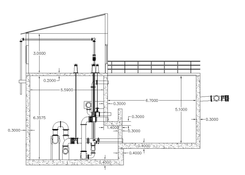
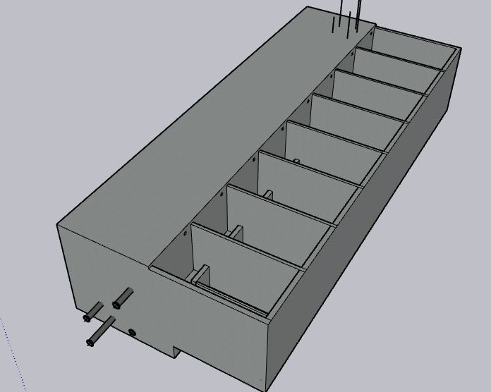
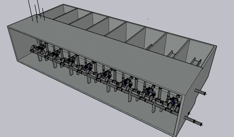
I have a 30mx13m Rapid Sand filter and a valve room (part of a water treatment plant) as indicated on the image below.

[URL unfurl="true"]https://res.cloudinary.com/engineering-com/image/upload/v1666258926/tips/RSF-3D_yxwb3k.bmp[/url]

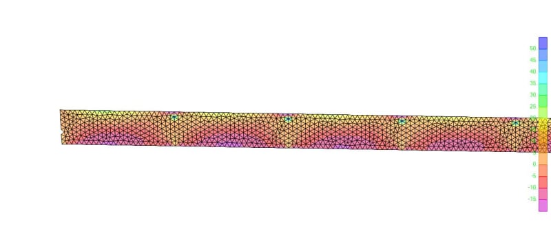
I have modelled the entire structure as 3D on gmsh (a meshing software) meshed the shells there and imported to sap2000 and added the columns at a joint for analysis. But one side of all columns and the wall supporting the interior column are all supported on 1.4m Long RC slab. I know it is not ideal to support it that way and that wall resting on the 1.4m slab should have to extend all the way to the foundation but it is near impossible because there are pipes and pipe fittings and a lot of valves. So, I had to see if I can support it this way. But I was expecting the negative top moment at that overhang slab to be relatively large but I am not getting the results I'm expecting. So, just to see some conservative result, I took the 1.4m long overhang slab as a 0.3m deep by 1m strip beam and modelled it with the right side fixed.
For the loads:-
1. I took half the 0.2m deep slab weight (for convenience) and adjusted it for a 1m strip and it is 14.4KN point load
2. For the HCB wall I took full weight of 3m height wall and is 11.7KN point load
3. For the 5kN/m2 Live Load on the top slab I took 7KN point load
4. For the wall self weight I took its weight on 1m strip as 28.8KN Point load
5. There is a 3.45m deep water load on the slab so I took 34.5KN/m distributed load for that
The result resembles what I'm expecting. Maximum support moment is around 144KN.m (about Φ20 @ 140mm)
For comparison, The result from the full 3D FEA analysis is only about 50kN.m for the top support moment on the overhang slab (around
Φ12 @ 170mm )
So is this acceptable why is there so much difference I know the 3D anlysis had to distribute to all members and had to be a little bit lower but is the difference not huge?

[URL unfurl="true"]https://res.cloudinary.com/engineering-com/image/upload/v1666258926/tips/RSF-3D_yxwb3k.bmp[/url]

I have modelled the entire structure as 3D on gmsh (a meshing software) meshed the shells there and imported to sap2000 and added the columns at a joint for analysis. But one side of all columns and the wall supporting the interior column are all supported on 1.4m Long RC slab. I know it is not ideal to support it that way and that wall resting on the 1.4m slab should have to extend all the way to the foundation but it is near impossible because there are pipes and pipe fittings and a lot of valves. So, I had to see if I can support it this way. But I was expecting the negative top moment at that overhang slab to be relatively large but I am not getting the results I'm expecting. So, just to see some conservative result, I took the 1.4m long overhang slab as a 0.3m deep by 1m strip beam and modelled it with the right side fixed.
For the loads:-
1. I took half the 0.2m deep slab weight (for convenience) and adjusted it for a 1m strip and it is 14.4KN point load
2. For the HCB wall I took full weight of 3m height wall and is 11.7KN point load
3. For the 5kN/m2 Live Load on the top slab I took 7KN point load
4. For the wall self weight I took its weight on 1m strip as 28.8KN Point load
5. There is a 3.45m deep water load on the slab so I took 34.5KN/m distributed load for that
The result resembles what I'm expecting. Maximum support moment is around 144KN.m (about Φ20 @ 140mm)
For comparison, The result from the full 3D FEA analysis is only about 50kN.m for the top support moment on the overhang slab (around
Φ12 @ 170mm )
So is this acceptable why is there so much difference I know the 3D anlysis had to distribute to all members and had to be a little bit lower but is the difference not huge?


